Head mounted display apparatus and backlight adjustment method thereof

Active Publication Date: 2015-07-02
QUANTA COMPUTER INC
View PDF8 Cites 16 Cited by
  • Summary
  • Abstract
  • Description
  • Claims
  • Application Information

AI Technical Summary

Problems solved by technology

Conventional CRT or LCD display cannot meet the requirements of large size and convenient portability at the same time.
Conversely, if the ambient ligh

Method used


Image

  • Head mounted display apparatus and backlight adjustment method thereof
  • Head mounted display apparatus and backlight adjustment method thereof
  • Head mounted display apparatus and backlight adjustment method thereof

Examples


first embodiment

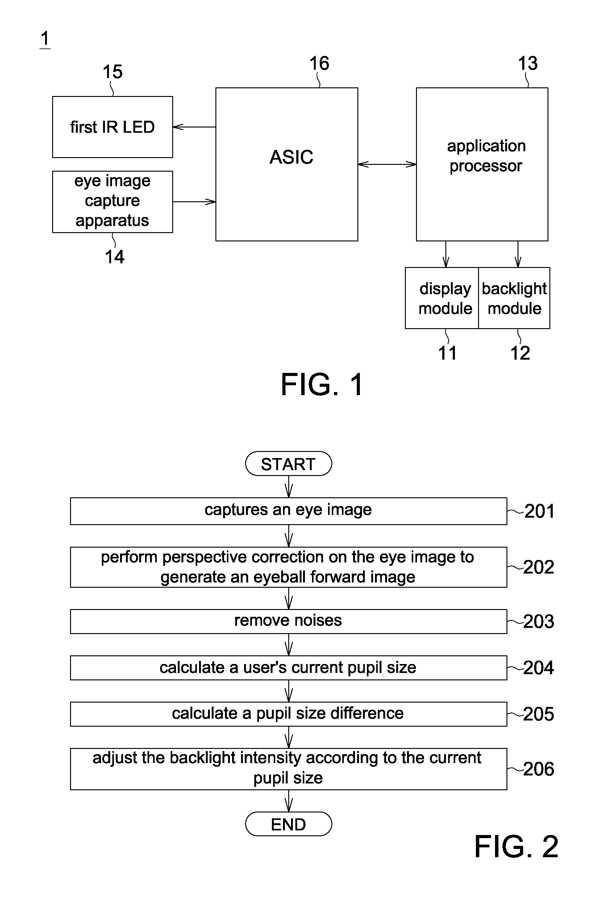
[0024]Referring to FIG. 1, a block diagram of a head mounted display apparatus according to a first embodiment is shown. The head mounted display apparatus 1 comprises a display module 11, a backlight module 12, an application processor 13, an eye image capture apparatus 14, a first infrared (IR) light emitting diode (LED) 15 and an application specific integrated circuit (ASIC) 16. The display module 11 can be realized by a pico projector. The application processor 13 communicated with the ASIC 16 through the universal serial bus (USB). The eye image capture apparatus 14 communicates with the ASIC 16 through a mobile industry processor interface (MIPI) or a parallel interface. The ASIC 16 turns on / off the first IR LED 15 through the general purpose input output (GPIO) interface.

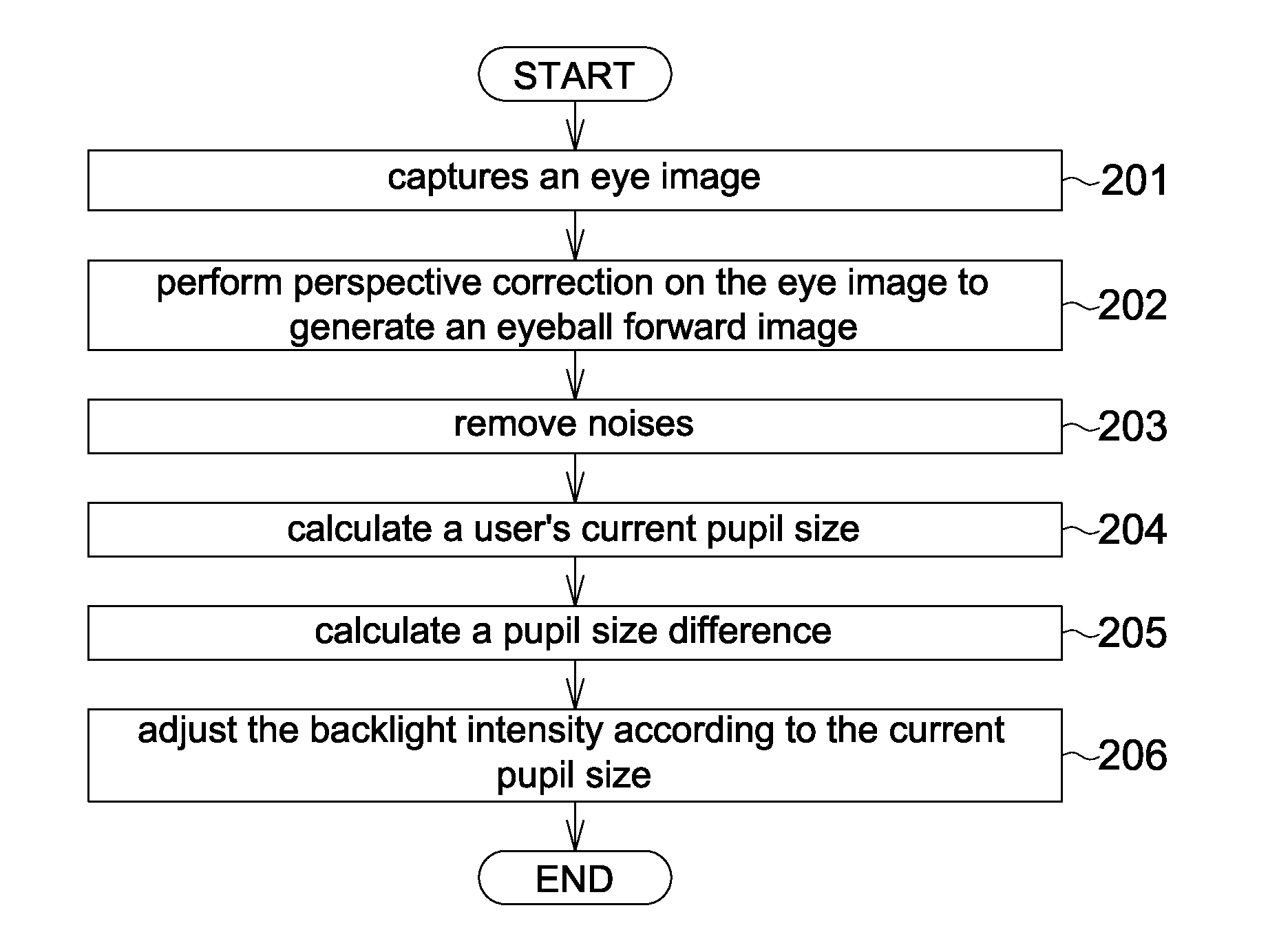
[0025]The backlight module 12, which can be realized by LED, provides a backlight to the display module 11. The eye image capture apparatus 14 captures an eye image. The first IR LED 15 provides a first auxi...

second embodiment

[0039]Referring to FIG. 8, FIG. 9 and FIG. 10. FIG. 8 is a block diagram of a head mounted display apparatus according to a second embodiment. FIG. 9 is a flowchart of a backlight adjustment method of a head mounted display apparatus according to a second embodiment. FIG. 10 is an appearance diagram of a head mounted display apparatus according to a second embodiment. The second embodiment is different from the first embodiment mainly in that the head mounted display apparatus 3 adjusts the backlight intensity through a front image captured by the front image captures apparatus 18, wherein the view angle of the front image captures apparatus 18 is about the same as the user's view angle.

[0040]The backlight adjustment method of the head mounted display apparatus 3 comprises following steps. Firstly, the method begins at step 401, the front image captures apparatus 18 captures a user's front image. Since the front image is used to detect the front ambient light luminance, the function...

third embodiment

[0041]Referring to FIG. 11 and FIG. 12. FIG. 11 is a block diagram of a head mounted display apparatus according to a third embodiment. FIG. 12 is an appearance diagram of a head mounted display apparatus according to a third embodiment. The third embodiment is different from the second embodiment mainly in that the head mounted display apparatus 5 adjusts the backlight intensity according to the ambient light luminance detected by an ambient light sensor (ALS) 19. The ALS 19 detects not only the front luminance, but also the ambient light luminance of the environment.

[0042]The head mounted display apparatus and the backlight adjustment method thereof disclosed in above embodiments are for exemplary purpose only. In some embodiments, the head mounted display apparatus can have more than two IR LEDs. Also, during the detection of the user's current pupil size, more than one IR LED can be turned on each time.


PUM


Abstract

A head mounted display apparatus and a backlight adjustment method thereof are disclosed. The head mounted display apparatus comprises a display module, a backlight module, an application processor, an eye image capture apparatus, an infrared (IR) light emitting diode (LED) and an application specific integrated circuit (ASIC). The backlight module provides a backlight to the display module. The eye image capture apparatus captures an eye image. The IR LED provides an auxiliary light source to the eye image capture apparatus. The ASIC calculates a current pupil size according to the eye image. The application processor adjusts the backlight intensity of the backlight module according to the current pupil size in an adjustment mode.

Description

[0001]This application claims the benefit of Taiwan application Serial No. 103100012, filed Jan. 2, 2014, the subject matter of which is incorporated herein by reference.BACKGROUND OF THE INVENTION[0002]1. Field of the Invention[0003]The invention relates in general to an electronic apparatus, and more particularly to a head mounted display apparatus and a backlight adjustment method thereof.[0004]2. Description of the Related Art[0005]Along with the advance in technology, people assimilate more and more information every day. The commonly seen multimedia play apparatus, network communication apparatus and computer apparatus are equipped with a CRT or LCD display for displaying images. However, the pixels and size of a displayed image depend on the size and efficiency of the display. Conventional CRT or LCD display cannot meet the requirements of large size and convenient portability at the same time. To resolve the above problem, an optical see-through head mounted display (HMD) ap...

Claims


Application Information

Patent Timeline
IPC IPC(8): G09G5/10G09G3/36G02B27/01
CPCG09G5/10G02B27/0172G02B2027/0178G09G3/3648G02B27/017G02B2027/0118G02B2027/0138G02B2027/014G09G3/001G09G3/3406G09G2320/0285G09G2330/12G09G2360/144
Inventor YANG, WEN-CHU
Owner QUANTA COMPUTER INC
Why Eureka
Try Eureka