
Method for operating a wheel slip control apparatus with compensated wheel speeds

a technology of a control apparatus and a speed compensation, which is applied in the direction of process and machine control, braking systems, instruments, etc., can solve the problems of large percentage error arising from the differences in revolution rate, the difference in the revolution rate is no longer exactly compensated, etc., and achieve the effect of very accurate wheel slip control

Active Publication Date: 2015-07-09
KNORR-BREMSE SYST FUER NUTZFAHRZEUGE GMBH
View PDF3 Cites 11 Cited by
  • Summary
  • Abstract
  • Description
  • Claims
  • Application Information

AI Technical Summary

Benefits of technology

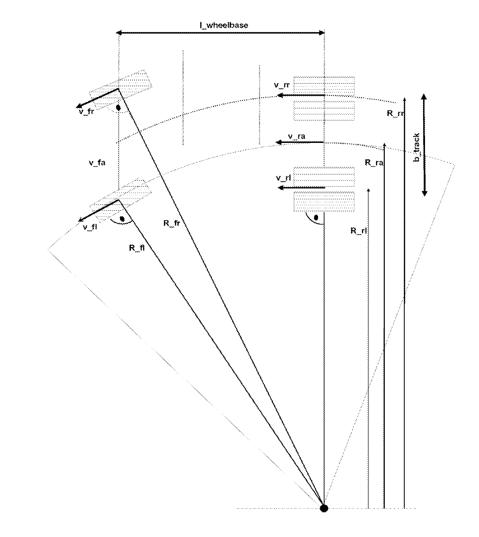
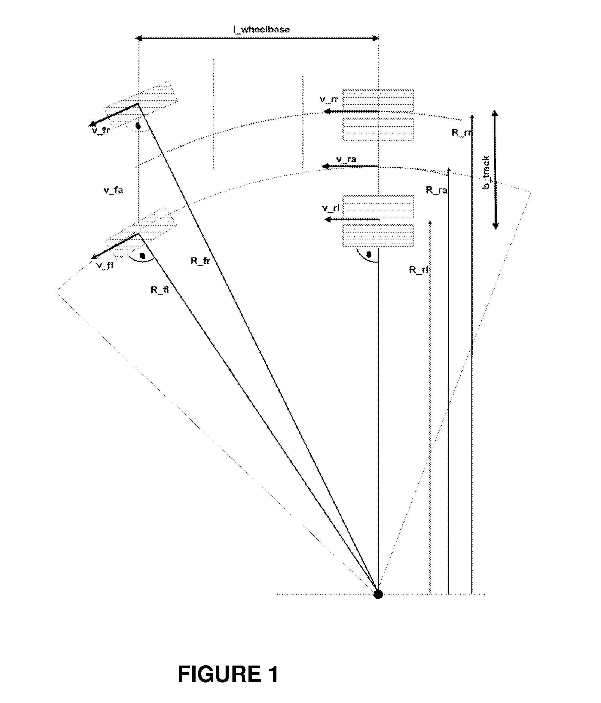
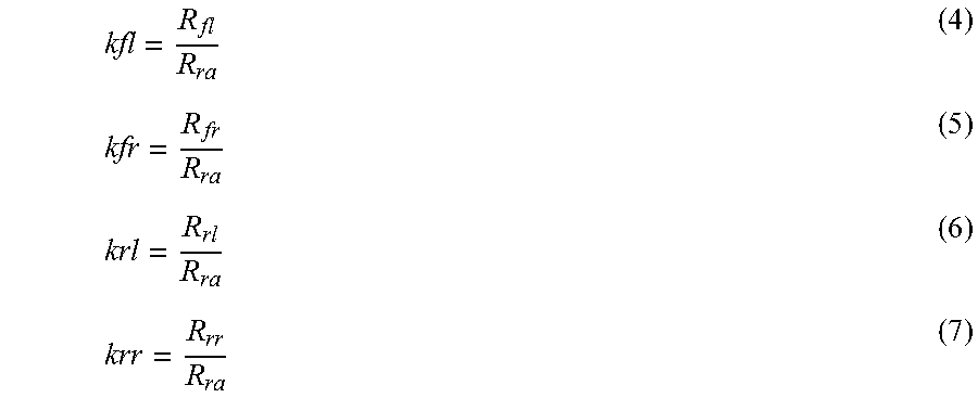
The present invention introduces a method to accurately control the wheel slip, especially when the turn radius changes during a turn. By calculating the radius of the turn for each individual wheel and comparing it with the speed of each wheel, the influence of braking or driving slip on the wheel can be determined independently. This allows for individualized control of the wheel slip, even in the case of changing turn radius. Furthermore, this method compensates for the difference in revolution rates between the wheels in a turn, resulting in a high-quality wheel slip control.

Problems solved by technology

If, however, the turn radius changes during braking, e.g. if the driver changes the steering angle with the vehicle already in a turn, then the difference in revolution rates between the wheels is no longer compensated exactly.
Above all, in the case of small brake slip during ABS control the percentage error arising from the differences in revolution rates can be very large.

Method used


Image

  • Method for operating a wheel slip control apparatus with compensated wheel speeds
  • Method for operating a wheel slip control apparatus with compensated wheel speeds
  • Method for operating a wheel slip control apparatus with compensated wheel speeds

Examples


Embodiment Construction

[0029]The method according to the present invention is carried out during wheel slip control such as ABS (Anti-lock Braking System) or TCS (Traction Control System), which controls or limits braking slip and / or drive slip occurring on wheels of a vehicle to an optimal slip. The wheel slip control is integrated within a vehicle dynamics control arrangement such as ESP (Electronic Stability Program).

[0030]The steering angle δ from a steering angle sensor, an actual yaw rate ωz—meas from a yaw rate detection device, as well as the speed of the vehicle ν from wheel speed sensors are available as sensor information to the controller of the vehicle dynamics control arrangement. Based on the[0031]steering angle δ and the speed of the vehicle ν, a reference-yaw rate ωz—ref, which represents a target yaw rate desired by the driver, is also calculated in the controller of the vehicle dynamics control arrangement.

[0032]Using the method described below, compensated wheel speeds may be calculate...


PUM


Abstract

A method and device for operating a wheel slip control apparatus, including determining wheel speeds of wheels compensated with respect to wheel speed differences during a turn as input variables for the wheel slip control apparatus, with which a) a neutral steering, understeering or oversteering driving condition of the vehicle is determined from the driving behavior during a turn, b) depending on the determined condition of the vehicle, either the reference or actual yaw rate is used to calculate a turn radius related to a selected point on the vehicle, c) wheel-related turn radii for at least some wheels are determined from the turn radius related to the selected point, d) reference factors are determined from the wheel-related turn radii and a common reference turn radius for at least some wheels, and e) the compensated wheel speeds are each determined from the reference factors and measured wheel speeds for at least some wheels, and f) the compensated wheel speeds are used as input variables for a wheel slip control apparatus.

Description

FIELD OF THE INVENTION[0001]The present invention relates to a method for operating a wheel slip control apparatus of a vehicle, including the determination of wheel speeds of wheels of the vehicle compensated in relation to wheel speed differences when turning as input variables for the wheel slip control apparatus, and of a wheel slip control apparatus operated according to such a method. Furthermore, the present invention also relates to a vehicle dynamics control device including such a wheel slip control apparatus.BACKGROUND INFORMATION[0002]The aim of wheel slip control such as ABS (Anti-lock Braking System) or TCS (Traction Control System) is to control or limit braking slip or drive slip occurring on wheels to an optimal slip. An optimal braking slip amounts to e.g. 12%. The wheel slip is determined by comparing the wheel speed of the wheel involved with a central reference speed. The measured wheel slip also contains, apart from the components longitudinal slip and braking ...

Claims


Application Information

Patent Timeline
IPC IPC(8): B60T8/171B60T8/1755B60T8/175G05D13/66G05D15/00
CPCB60T8/171G05D13/66G05D15/00B60T8/175Y10T477/10B60W2510/207B60T8/17552B60T2230/02B60T8/17551B60T8/1761B60T2230/00B60T2240/00B60T2250/00B60T2270/12B60T2270/202B60T8/172B60T8/17616B60T2201/16B60T2210/24
Inventor VORREITER, MARTIN
Owner KNORR-BREMSE SYST FUER NUTZFAHRZEUGE GMBH
Learn More