
Method and device for controlling the reference speed of a down-hill speed controller

a speed controller and reference speed technology, applied in the direction of braking systems, vehicles, positions/courses/altitude control, etc., can solve the problems of unfavorable vehicle speed increase, and unnecessary amount of actual speed of the vehicl

Active Publication Date: 2015-07-09
SCANIA CV AB
View PDF11 Cites 23 Cited by
  • Summary
  • Abstract
  • Description
  • Claims
  • Application Information

AI Technical Summary

Benefits of technology

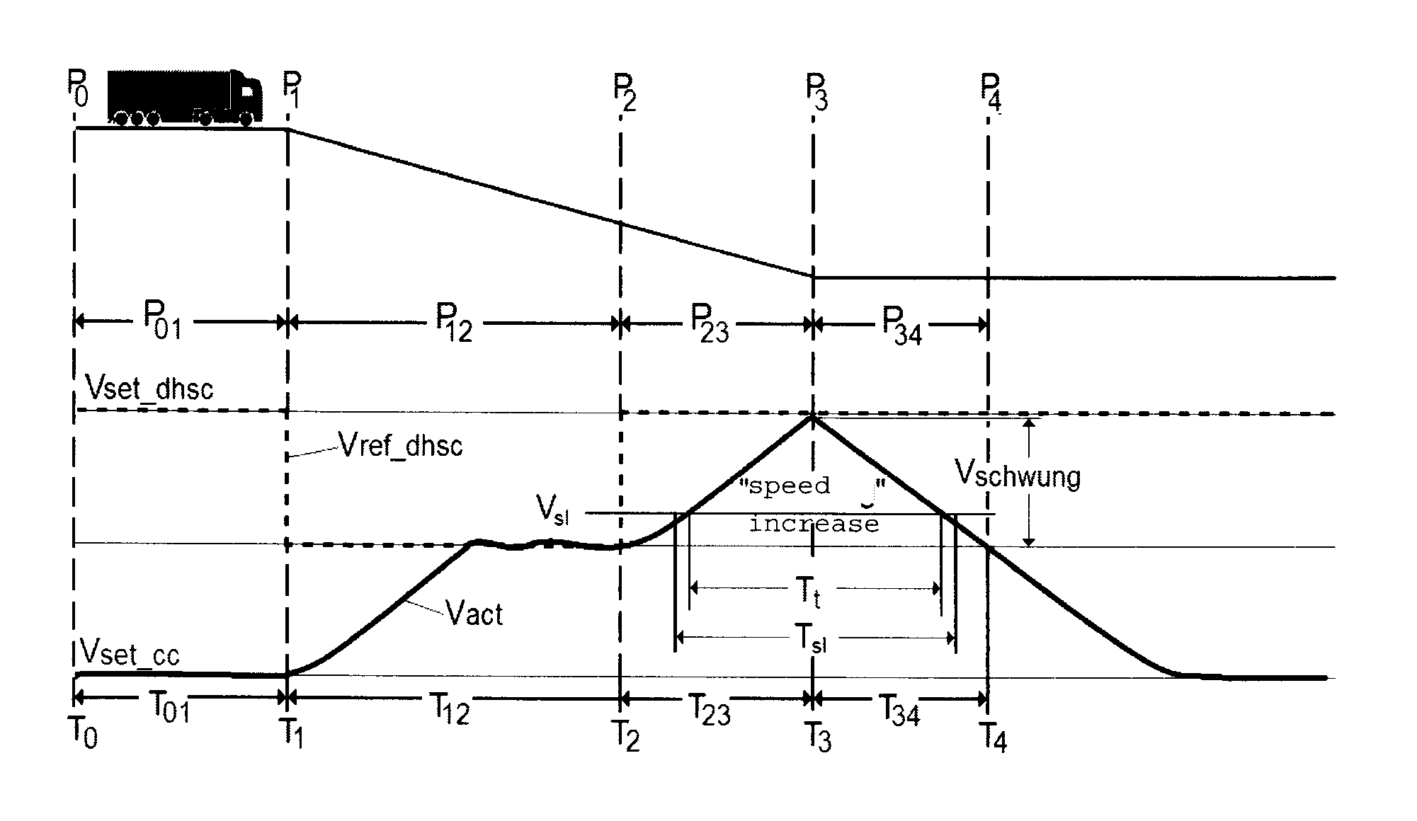
The present invention provides a system for controlling the speed of a vehicle during downhill driving. By using an increased reference speed, the system can increased the actual vehicle speed at the end of a downhill gradient, resulting in more kinetic energy that can be utilized by the vehicle. The increased speed is determined based on rules regarding speed limits and infringements, and is coordinated with the control of the vehicle's cruise control system to maximize the use of the available kinetic energy. The system accurately simulates the future speed profile of the vehicle based on map data in front of it, ensuring precise control. The technical effect of this invention is an improved driving experience and increased efficiency of the vehicle's downhill driving control system.

Problems solved by technology

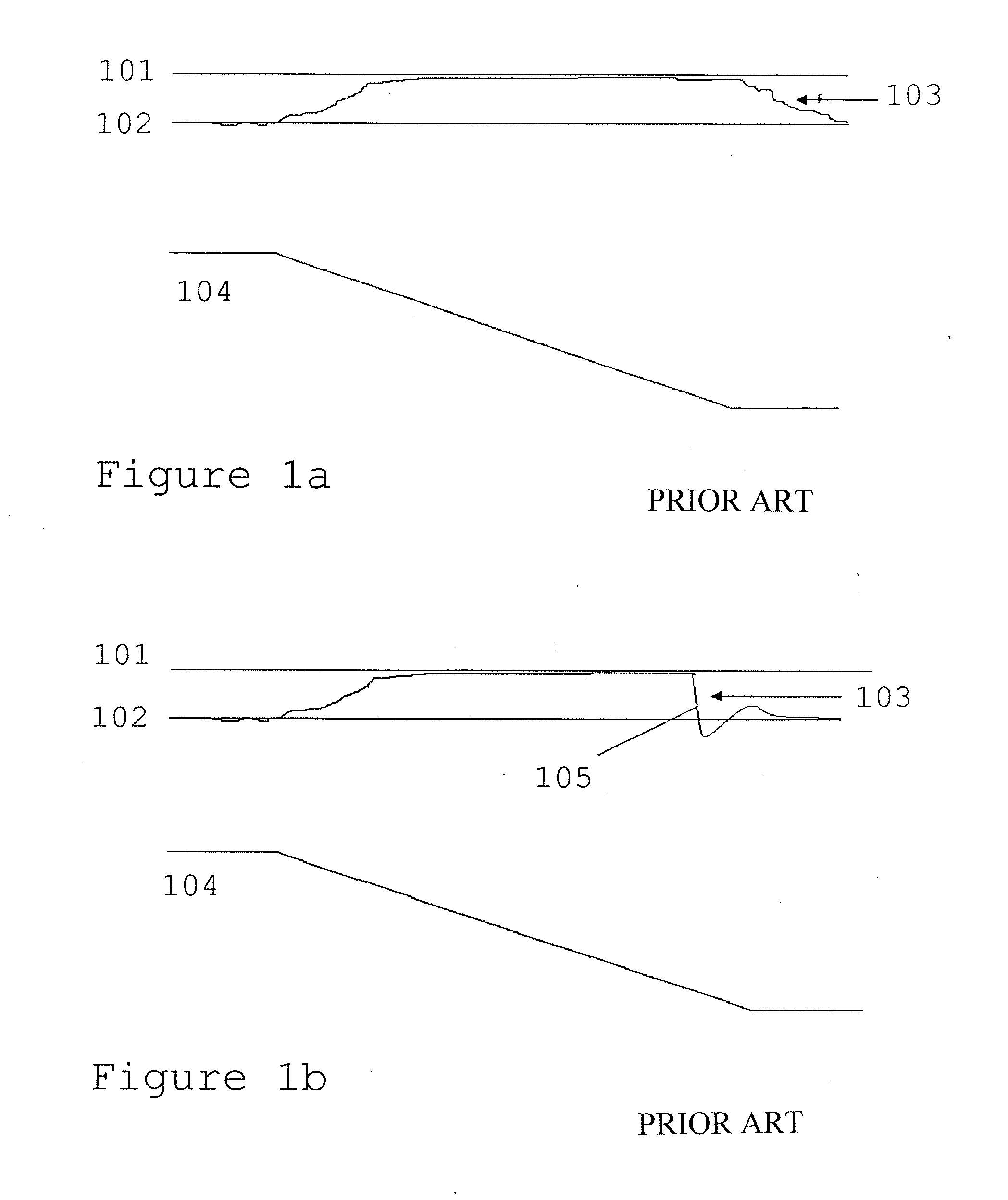
However, because of other vehicles on the road, and / or speed limits the vehicle may not be permitted to freely increase its speed on downhill gradients, for example.
In other words, this driver behaviour results in the vehicle leaving the downhill gradient at a low actual speed vact 103, which is not efficient from the point of view of fuel economy.
However, this would lead to an unnecessary amount of the actual speed of the vehicle vact being braked away over the downhill gradient, which is not optimum from the point of view of fuel economy and not optimum from the point of view of driving time.

Method used


Image

  • Method and device for controlling the reference speed of a down-hill speed controller
  • Method and device for controlling the reference speed of a down-hill speed controller
  • Method and device for controlling the reference speed of a down-hill speed controller

Examples


Embodiment Construction

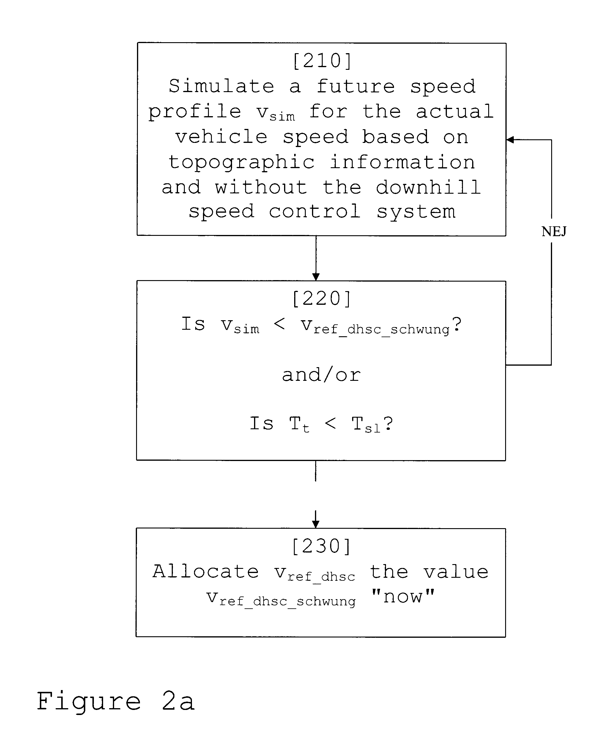
[0037]The present invention relates to governing a reference speed vref—dhsc for a downhill speed control system in a vehicle in connection with a downhill gradient, which results in an increased reference speed vref—dhsc—schwung in the final part of the gradient. FIG. 2a shows a schematic flow diagram for the invention.

[0038]In a first step 210 for the method of the present invention, at least one future speed profile vsim of the vehicle is simulated for a section of road in front of the vehicle. Here the section of road can correspond to a horizon, which is equivalent to a section of road of for example 1-2 km in front of the vehicle in its direction of travel. The simulation is carried out on the basis of topographic information, which can consist of topographic mapping information combined with positioning information for example.

[0039]According to one embodiment of the invention, the simulation can also be based on ignoring the effect of the downhill speed control system, that ...


PUM


Abstract

A system for governing a reference speed vref<sub2>—< / sub2>dhsc for a downhill speed control system in a vehicle in connection with a downhill gradient. A simulation unit simulates at least one future speed profile vsim for an actual vehicle speed over a section of road in front of the vehicle, based on topographic information. An establishing unit establishes whether the reference speed vref<sub2>—< / sub2>dhsc is to be allocated an increased reference speed vref<sub2>—< / sub2>dhsc<sub2>—< / sub2>schwung. This establishing is based on a comparison of the simulated future speed profile vsim with a permitted magnitude of the increased reference speed vref<sub2>—< / sub2>dhsc<sub2>—< / sub2>schwung and / or with an infringement speed vsl. An allocation unit allocates the value of the increased reference speed vref<sub2>—< / sub2>dhsc<sub2>—< / sub2>schwung to the reference speed vref<sub2>—< / sub2>dhsc if this has been established.

Description

[0001]The present application is a 35 U.S.C. §§371 National Phase conversion of PCT / SE2013 / 050607, filed May 28, 2013, which claims priority of Swedish Patent Application No. 1250644-0, filed Jun. 19, 2012, the contents of which are incorporated by reference herein. The PCT International Application was published in the English language.TECHNICAL FIELD[0002]The present invention relates to a method for governing a reference speed vref<sub2>—< / sub2>dhsc for a downhill speed control system for a vehicle and a system for governing a reference speed vref<sub2>—< / sub2>dhsc for a downhill speed control device.[0003]The present invention also relates to a computer program and a computer program product that execute the method in accordance with the invention.BACKGROUND[0004]Motor vehicles, and especially heavy motor vehicles such as trucks and buses, are affected by gravity on downhill gradients in such a way that their speed increases. For this reason, many heavy v...

Claims


Application Information

Patent Timeline
IPC IPC(8): B60W30/14B60T7/12G07C5/08B60T1/06
CPCB60W30/146B60T1/062B60T7/12B60W2720/106B60W2520/10B60W2520/105B60W2720/10G07C5/08B60K31/00B60T7/18B60W30/18072B60W2552/20G07C5/002B60W50/0097B60T10/00B60W10/196B60W30/14G01P1/12G01P1/122G07C5/0841B60T2201/04
Inventor JOHANSSON, OSKAROGREN, MIKAELSWARTLING, FREDRIK
Owner SCANIA CV AB
Learn More