
Inverter and bobbin thereof

a technology of inverter and bobbin, which is applied in the field of inverter, can solve the problems of ineffective utilization of conventional inverter for bearing voltage as high as 4000 volts, inability to effectively utilize conventional inverter for the practical application of high-voltage devices or apparatuses, and risk of arc burn phenomena, so as to reduce the disadvantages of inverter and reduce the cost of operation. , the effect of low voltage resistan

Inactive Publication Date: 2015-07-09
DELTA ELECTRONICS INC
View PDF5 Cites 4 Cited by
  • Summary
  • Abstract
  • Description
  • Claims
  • Application Information

AI Technical Summary

Benefits of technology

The present invention provides an improved inverter and bobbin design to overcome the challenges faced by conventional inverters in terms of low voltage-resistance, limited versatility, and potential for ignition or arc burn phenomena. By utilizing a wire groove and partially disposing a first insulated wire in the groove, the first outlet is staggered with the winding portion, thereby avoiding short circuit and arc burn phenomena. Additionally, the first and second outlets of the first insulated wire can be connected with different pins of the base to meet various needs, enhancing versatility and reducing research and development costs.

Problems solved by technology

However, an arc burn phenomena of the conventional inverter utilizing the conventional bobbin is easily occurred, such that the conventional inverter cannot be effectively utilized for bearing voltage as high as 4000 volts.
Not only the risk of arc burn phenomena is not eliminated, but also the conventional inverter cannot be effectively utilized for the practical applications of the high-voltage devices or apparatuses due to the limitations of the winding position and the winding method of the winding 11, which lacks of versatility.

Method used


Image

  • Inverter and bobbin thereof
  • Inverter and bobbin thereof
  • Inverter and bobbin thereof

Examples


Embodiment Construction

[0015]The present disclosure will now be described more specifically with reference to the following embodiments. It is to be noted that the following descriptions of preferred embodiments of this disclosure are presented herein for purpose of illustration and description only. It is not intended to be exhaustive or to be limited to the precise form disclosed.

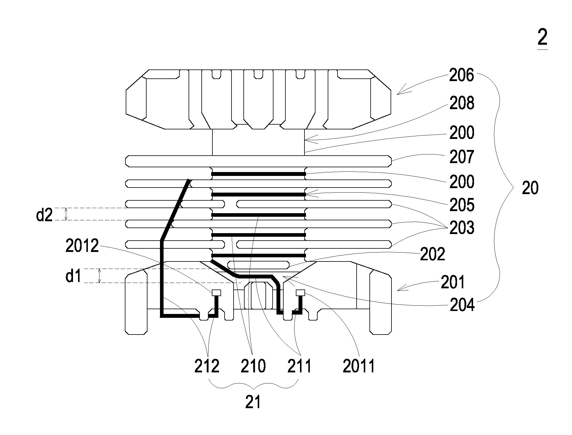
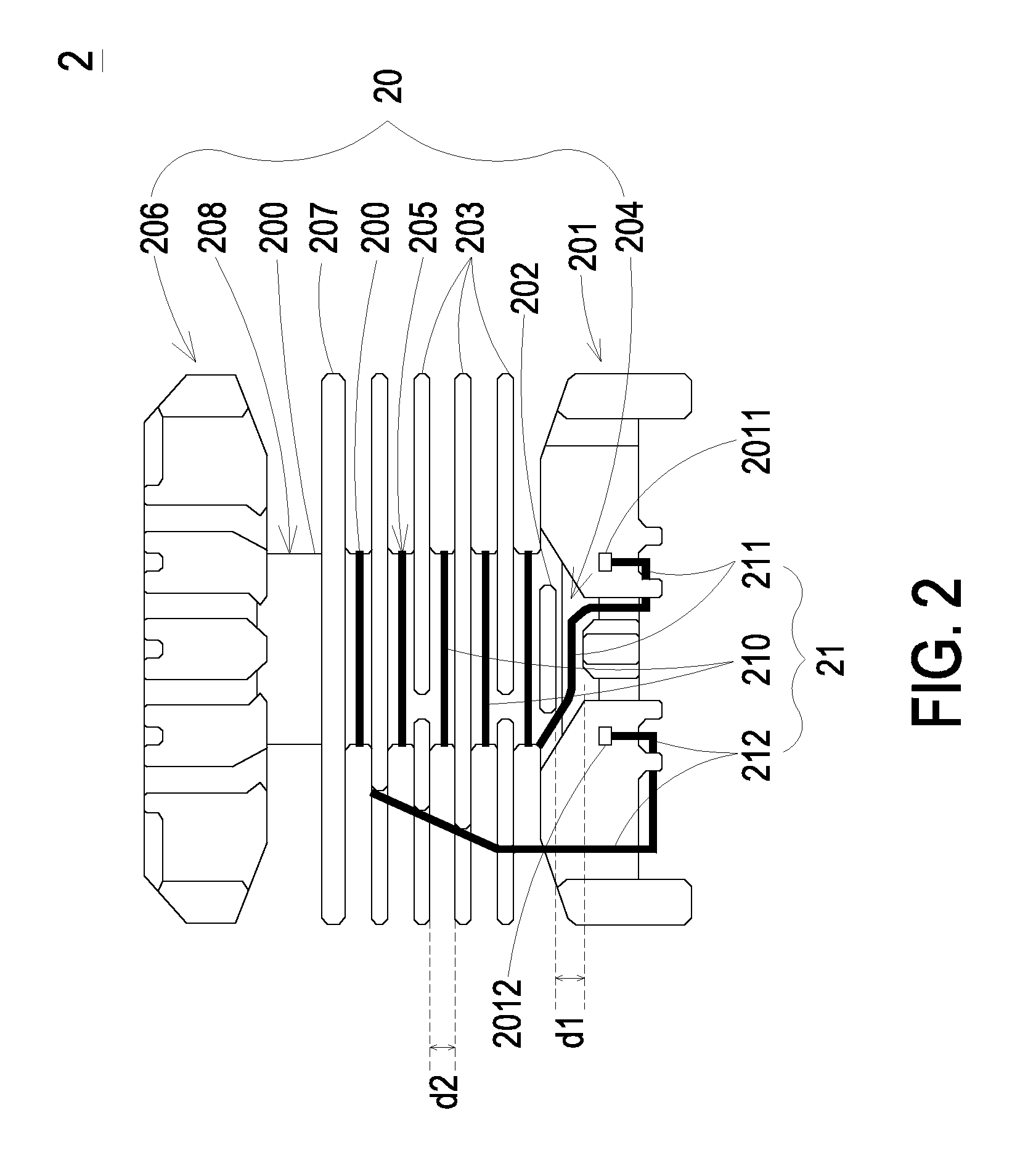
[0016]Please refer to FIG. 2. FIG. 2 schematically illustrates the bottom view of an inverter and a bobbin thereof according to an embodiment of the present invention. As shown in FIG. 2, an inverter 20 of the present invention includes a bobbin 20 and a first insulated wire 21. The bobbin 20 includes a main body 200, a first base 201, a first plate 202 and a plurality of second plates 203, and the first insulated wire 21 has a winding portion 210 and a first outlet 211. In this embodiment, the first base 201, which is not limited to a first pin base, is disposed on one side of the main body 200 and connected with the main body...


PUM


Abstract

An inverter includes a bobbin and a first insulated wire. The bobbin includes a main body, a first base disposed on one side of the main body and connected with the main body, a first plate disposed between the main body and the first base, among which a wire groove is formed between the first plate and the first base, and a plurality of second plates disposed on the main body for forming a plurality of first winding grooves on the main body. The first insulated wire has a winding portion disposed in the first winding grooves and a first outlet partially disposed in the wire groove, such that the first outlet is staggered with the winding portion, thereby avoiding the short circuit phenomena of the first insulated wire caused by the tear abrasion, avoiding the arc burn phenomena, and having high voltage-resistance.

Description

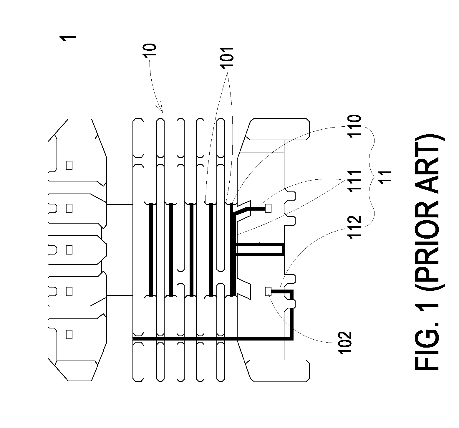
TECHNICAL FIELD[0001]The present disclosure relates to an inverter, and more particularly to an inverter and a bobbin thereof.BACKGROUND[0002]Inverters, which are indispensable elements, play an important role in lots types of electronic devices or apparatuses. With growing and developing of the applications of each type of high-voltage models in the industry, inverters are required to have high voltage-resistance and high versatility in order to meet the practical demands and the product trends.[0003]The requirement of the voltage-resistance of a single inverter rises from 3000 volts resistance to 4000 volts resistance in mainstream products of inverters. However, an arc burn phenomena of the conventional inverter utilizing the conventional bobbin is easily occurred, such that the conventional inverter cannot be effectively utilized for bearing voltage as high as 4000 volts. Please refer to FIG. 1. FIG. 1 schematically illustrates the bottom view of a conventional inverter and a co...

Claims


Application Information

Patent Timeline
IPC IPC(8): H01F27/32H01F27/28
CPCH01F27/2823H01F27/325H01F27/2828
Inventor CHEN, PI-FANZHANG, ZHI-LIANGCHIU, CHIH-YUNGHSU, SU-CHIUNG
Owner DELTA ELECTRONICS INC
Learn More