Driving circuit and driving method

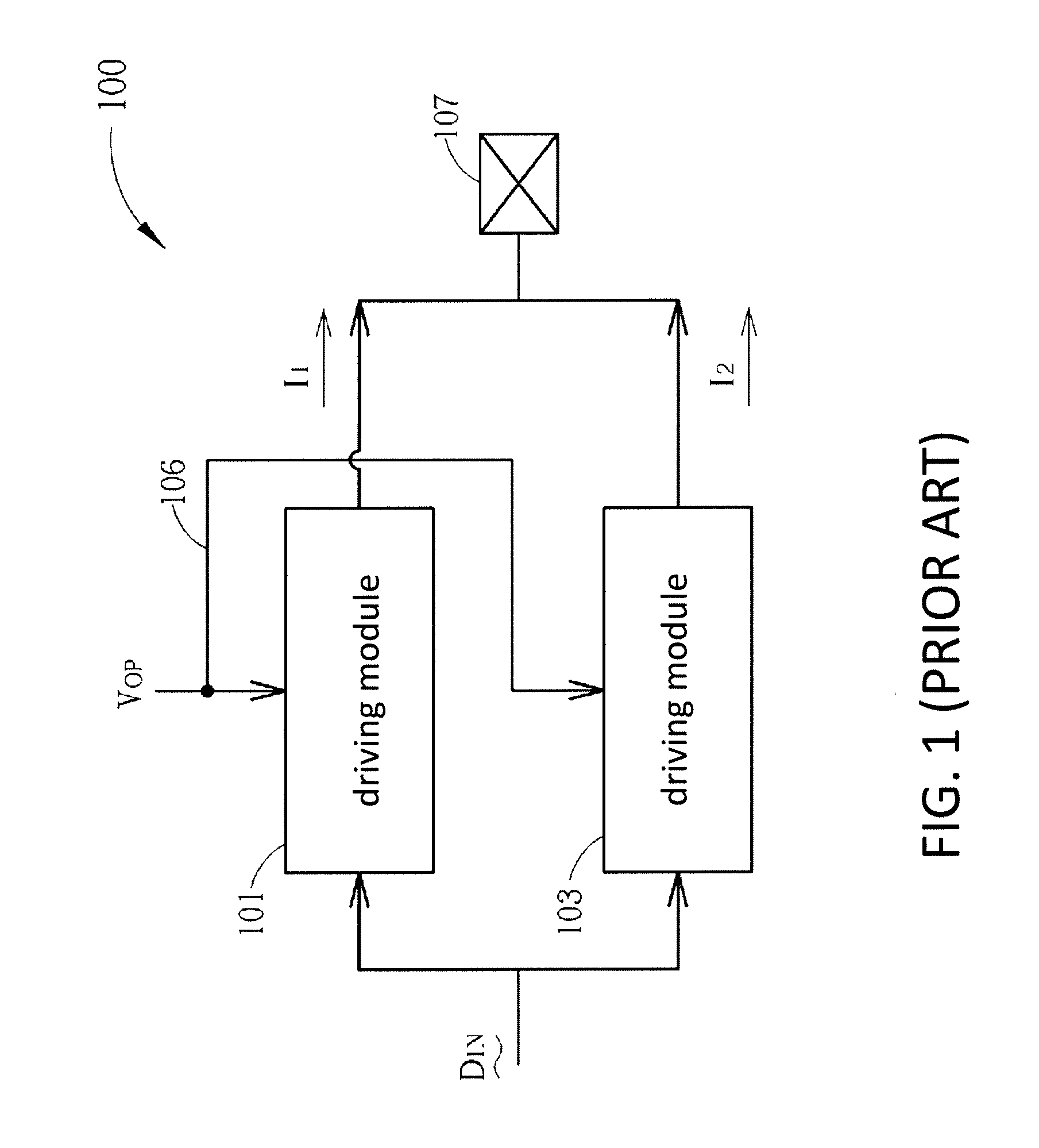
a driving circuit and driving method technology, applied in pulse technique, oscillator, instruments, etc., can solve the problems of leaking current, inability to fully deactivate the driving module b>103/b>, and inability to fix and vary the input signal d/sub>in /sub>, so as to achieve the effect of not increasing the circuit area

Active Publication Date: 2015-07-09
MEDIATEK INC
View PDF1 Cites 1 Cited by
  • Summary
  • Abstract
  • Description
  • Claims
  • Application Information

AI Technical Summary

Benefits of technology

[0011]According to the aforementioned embodiments, by providing protection voltage in a mode operating in higher voltage, the driving circuit can function properly in different operating voltages without increasing circuit area.

Problems solved by technology

However, the input signal DIN is not fixed and varies from time to time.
As a result, the driving module 103 cannot be fully deactivated and some current is leaked.

Method used


Image

  • Driving circuit and driving method
  • Driving circuit and driving method
  • Driving circuit and driving method

Examples


Embodiment Construction

[0021]Some embodiments of the present invention are described in details below. However, in addition to the descriptions given below, the present invention can be implemented in alternative ways, and the scope of the present invention is not limited other than by the scope of the claims. Moreover, for better understanding and clarity of the description, some components in the drawings may not necessarily be drawn to scale, wherein some may be exaggerated relative to others, and irrelevant parts are omitted.

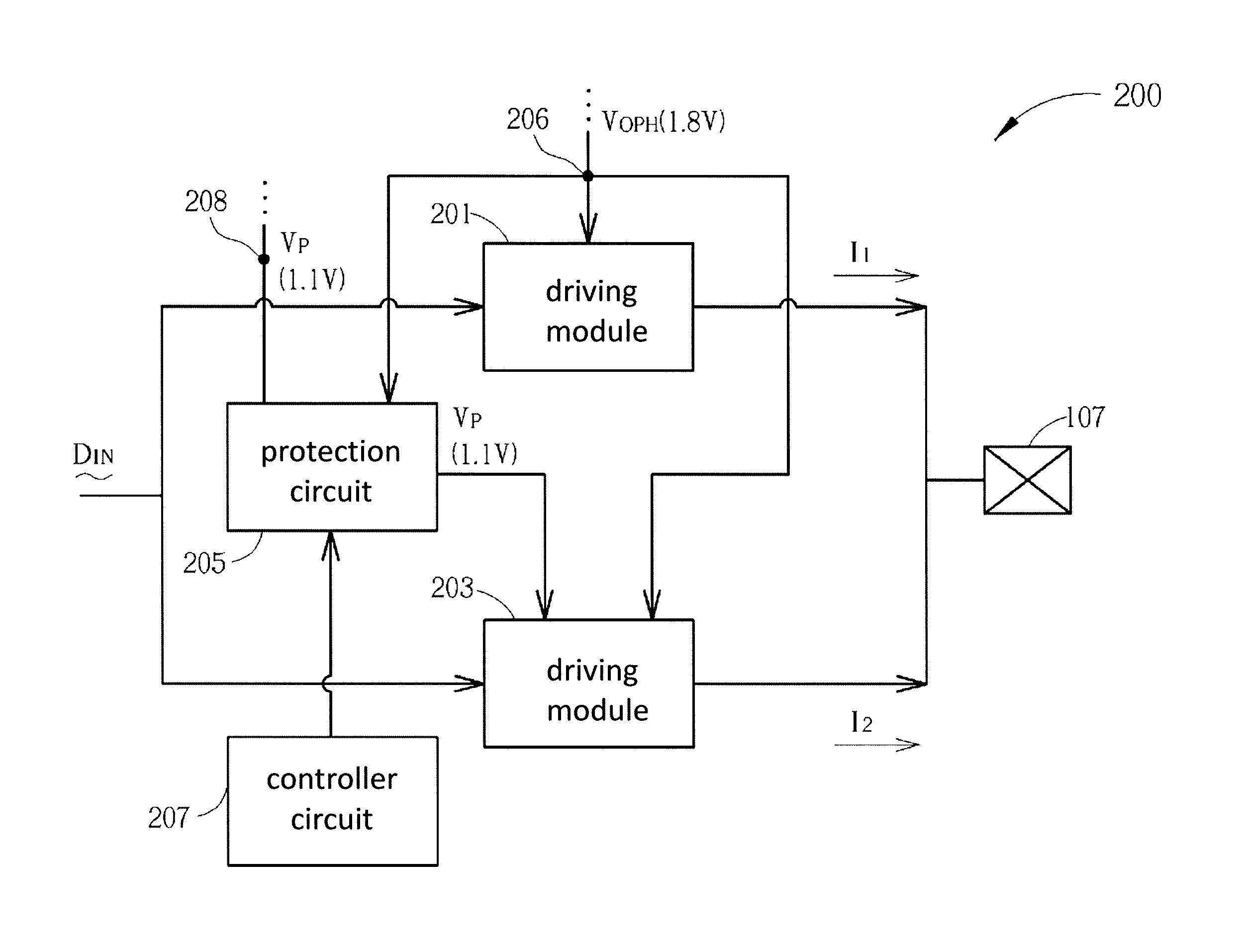
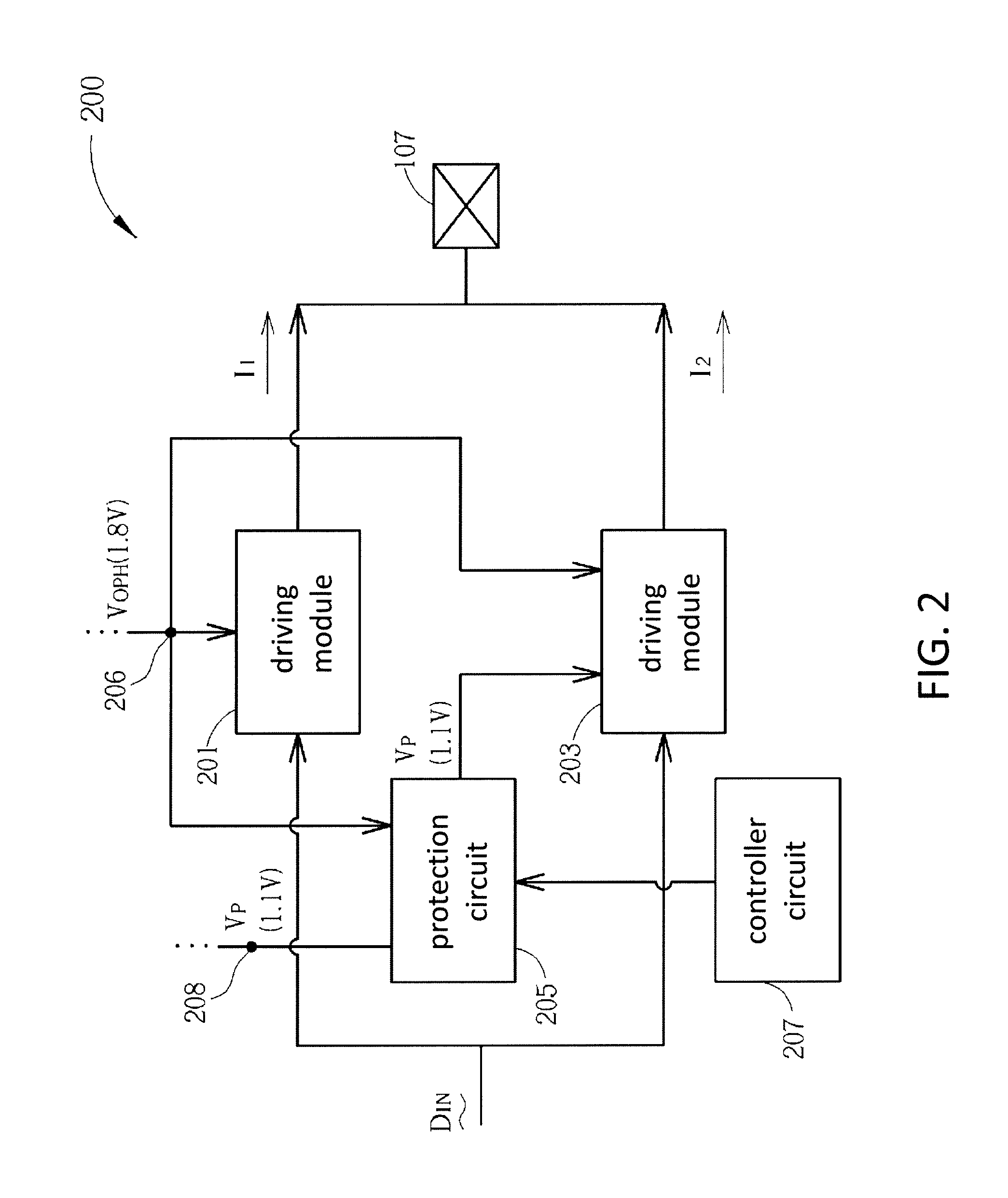
[0022]FIG. 2 depicts a block diagram of driving circuit 200 operating in a first mode in accordance with an embodiment of the present invention. Note that although the embodiment operating at 1.8V and 1.2V as in the prior art, it does not mean that the driving circuit 200 can only operate at these two voltages. Those skilled in the art will understand that the driving circuit 200 can be configured to adapt to various electronic devices or components to be driven. As shown in FIG. ...


PUM


Abstract

A driving circuit includes a first driving module, configured to operate at a first operating voltage in a first mode and configured to be deactivated in a second mode; and a second driving module, wherein at least part of the second driving module operates at a protection voltage in the first mode and operates at a second operating voltage in the second mode, wherein the second operating voltage and the protection voltage are lower than the first operating voltage.

Description

CROSS REFERENCE TO RELATED APPLICATIONS[0001]This application is a Divisional of application Ser. No. 13 / 934,492, filed Jul. 3, 2103, which claims priority under 35 U.S.C. 119 to Taiwan patent application, TW101128008, filed on Aug. 3, 2012, the disclosures of which are incorporated herein by reference.BACKGROUND OF THE INVENTION[0002]1. Field of the Invention[0003]The present invention relates to a driving circuit and related driving method, and more particularly, to a driving circuit and driving method operating at multiple operating voltages.[0004]2. Description of the Prior Art[0005]FIG. 1 illustrates a block diagram of a driving circuit 100 in the prior art. As shown in FIG. 1, the driving circuit 100 comprises driving modules 101 and 103. Driving currents I1 and I2 are generated and outputted to a connection pad 107 according to an input signal DIN. The driving circuit 100 includes an operating voltage receiving end 106 to receive operating voltage VOP for the driving modules ...

Claims


Application Information

Patent Timeline
Patent Type & Authority Applications(United States)
IPC IPC(8): H03K19/0175
CPCH03K19/0175G05F3/02
Inventor LIU, HSIAN-FENGTYAN, EER-WENCHEN, CHAO-AN
Owner MEDIATEK INC
Why Eureka
Try Eureka