Power amplifier circuit

a power amplifier and circuit technology, applied in gated amplifiers, amplifiers, amplifiers with semiconductor devices/discharge tubes, etc., can solve problems such as circuit area increase, and achieve the effect of increasing circuit area

Pending Publication Date: 2021-10-21
MURATA MFG CO LTD
View PDF4 Cites 0 Cited by
  • Summary
  • Abstract
  • Description
  • Claims
  • Application Information

AI Technical Summary

Benefits of technology

[0004]In a case where a mode selection switch for performing switching in accordance with a mode and a band selection switch for performing switching in accordance with a frequency band are integrated together as in United States Patent Application Publication No. 2016 / 0028353, matching elements for the respective modes are provided between the mode selection switch and power amplifiers. Furthermore, in a case where optimum matching is to be achieved in each of the bands, matching circuits for the respective bands are provided on the output side of the band selection switch. These matching circuits result in an increase in circuit area.

Problems solved by technology

These matching circuits result in an increase in circuit area.

Method used


Image

  • Power amplifier circuit
  • Power amplifier circuit
  • Power amplifier circuit

Examples


first embodiment

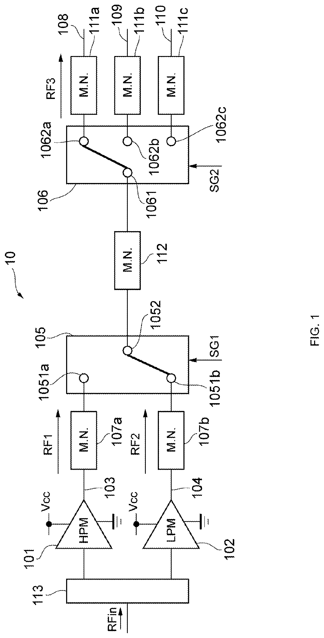
[0070]Exemplary embodiments of the present disclosure have been described above. The power amplifier circuit 10 includes the amplification path 103 including one or more power amplifiers 101 configured to generate the amplified signal RF1 from the input signal RFin when in the HPM, and the amplification path 104 including one or more power amplifiers 102 configured to generate the amplified signal RF2 from the input signal RFin when in the LPM.

[0071]The power amplifier circuit 10 includes the switching circuit 105 including the input terminals 1051a and 1051b and the output terminal 1052. The input terminal 1051a is connected to the amplification path 103, and the input terminal 1051b is connected to the amplification path 104. The switching circuit 105 is configured to electrically connect either the amplification path 103 or the amplification path 104 and the output terminal 1052 to each other in response to the control signal SG1 indicating either the HPM or the LPM.

[0072]The po...

third embodiment

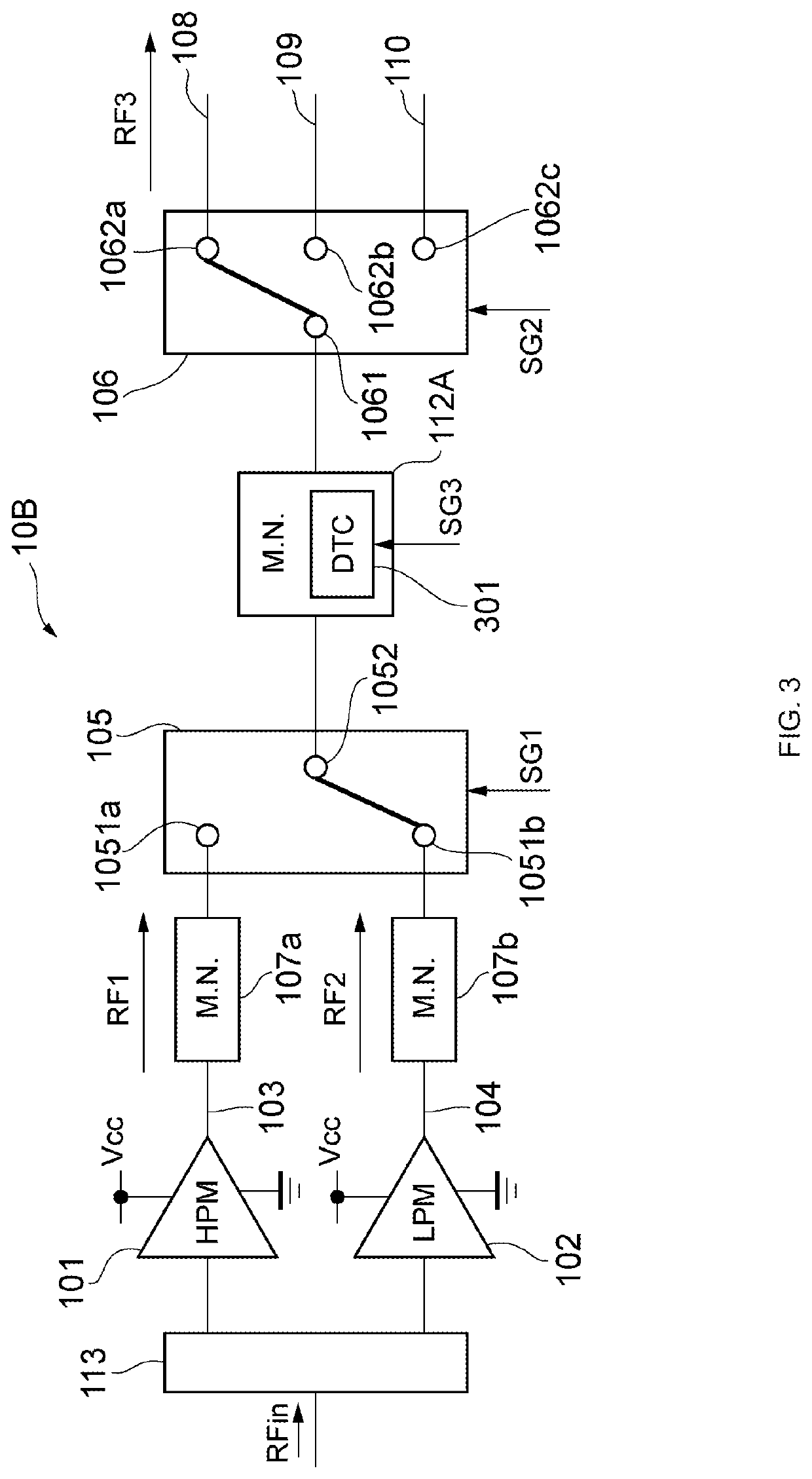
[0077]The power amplifier circuit 10B includes the variable matching circuit 112A, which is a variable matching circuit whose characteristic is adjustable. In the power amplifier circuit 10B, the variable matching circuit 112A includes the variable capacitor 301. In the power amplifier circuit 10B, the adjustable capacitance value of the variable capacitor 301 enables use of the integrated matching element, which eliminates the necessity for using the matching circuits 111a, 111b, and 111c that are included in the power amplifier circuit 10, and thus the circuit area to be used for matching can be reduced. Furthermore, optimized impedance matching makes it possible to reduce current consumption in the power amplifier circuit 10B.

[0078]In the power amplifier circuit 10, the switching circuit 105 and the switching circuit 106 may be disposed on or in a single IC chip. Alternatively, in the power amplifier circuit 10, the switching circuit 105 and the switching circuit 106 may be disp...

fourth embodiment

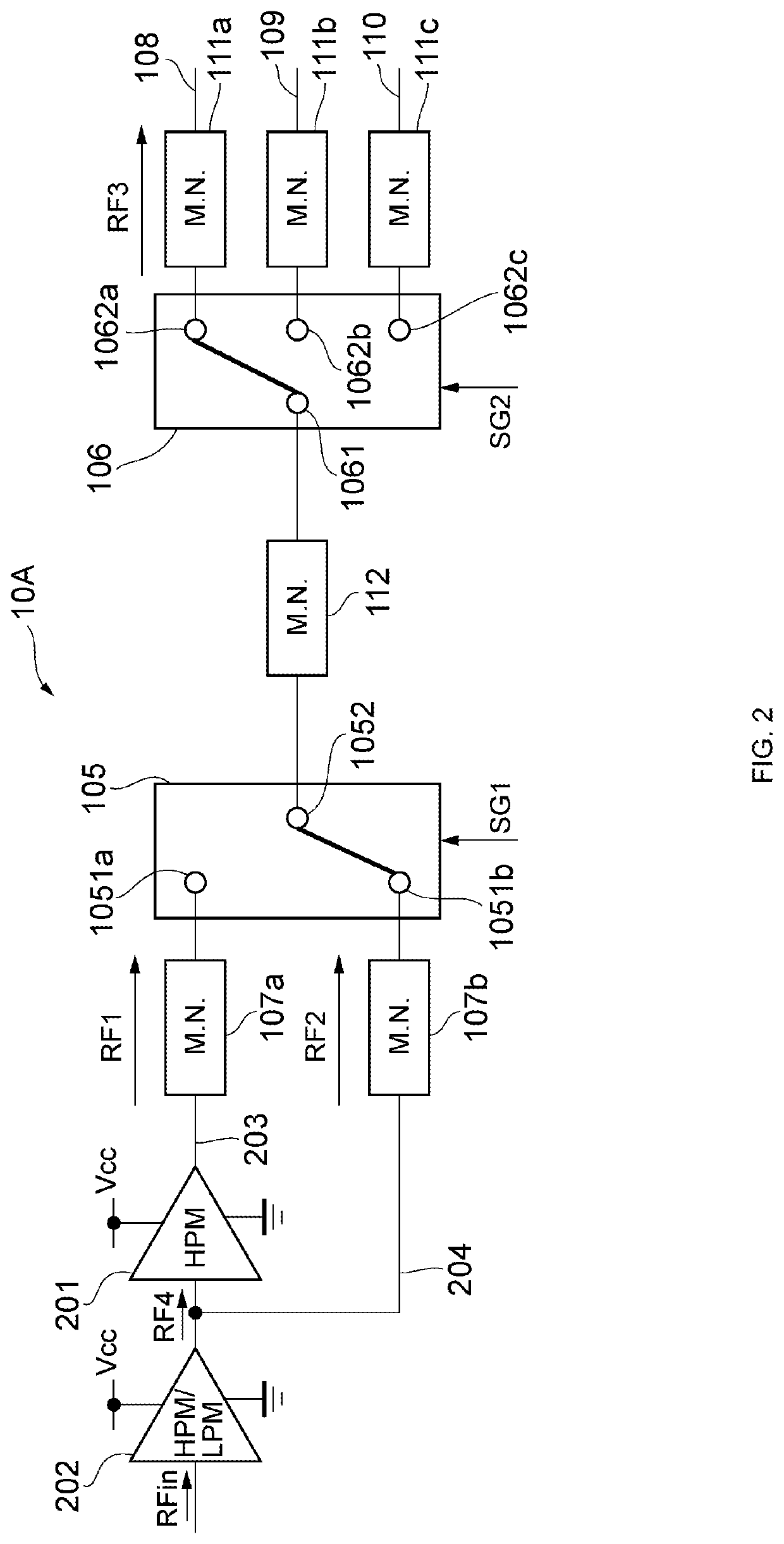
[0081]The power amplifier circuit 40 includes the amplification path 403 including one or more power amplifiers 4011 and 4012 configured to generate the amplified signal RF1 from the input signal RFin when in the HPM, and the amplification path 404 including one or more power amplifiers 402 configured to generate the amplified signal RF2 from the input signal RFin when in the LPM.

[0082]The power amplifier circuit 40 includes the switching circuit 405 including the terminal 4051 and the terminal 4052. The terminal 4051 is connected to the amplification path 403, and the terminal 4052 is connected to the amplification path 404. The switching circuit 405 is configured to be in an off state when in the HPM and be in an on state when in the LPM in response to the control signal SG4 indicating either the HPM or the LPM.

[0083]The power amplifier circuit 40 includes the switching circuit 106 including the input terminal 1061 and the output terminals 1062a, 1062b, and 1062c and configured t...


PUM


Abstract

A power amplifier circuit includes a first amplification path including a first power amplifier, a second amplification path including a second power amplifier, a first switching circuit configured to electrically connect either the first amplification path or the second amplification path and a first output terminal to each other, a second switching circuit configured to electrically connect an input terminal and any one of a plurality of second output terminals to each other, and a matching circuit configured to electrically connect the first output terminal and the input terminal to each other and achieve impedance matching between the first output terminal and the input terminal.

Description

CROSS REFERENCE TO RELATED APPLICATION[0001]This application claims priority from Japanese Patent Application No. 2020-073066 filed on Apr. 15, 2020. The content of this application is incorporated herein by reference in its entirety.BACKGROUND OF THE DISCLOSUREField of the Disclosure[0002]The present disclosure relates to a power amplifier circuit.Description of the Related Art[0003]Power amplifier circuits that amplify radio-frequency (RF) signals are used in communication using mobile terminals, such as mobile phones. There is a power amplifier circuit that switches, for the purpose of increasing efficiency, between a low power mode in which low power amplification is performed and a high power mode in which high power amplification is performed. Switching between the modes is performed by a switch. United States Patent Application Publication No. 2016 / 0028353 discloses a configuration including a switch for switching between paths in accordance with a mode and a switch for switc...

Claims


Application Information

Patent Timeline
Patent Type & Authority Applications(United States)
IPC IPC(8): H03F1/56H03F3/72H03F3/24H03F3/195
CPCH03F1/565H03F3/72H03F2200/318H03F3/195H03F2200/451H03F3/245
Inventor GOTO, SATOSHISATO, TOMOAKINAMIE, HISANORI
Owner MURATA MFG CO LTD
Why Eureka
Try Eureka