Drive circuit

a technology of drive circuit and gate, applied in the direction of electric variable regulation, process and machine control, instruments, etc., can solve the problems of emi noise, large device size of constant current drive mode compared with on-resistance drive mode, etc., and achieve the effect of large circuit area

Active Publication Date: 2016-04-28
MITSUBISHI ELECTRIC CORP
View PDF6 Cites 0 Cited by
  • Summary
  • Abstract
  • Description
  • Claims
  • Application Information

AI Technical Summary

Benefits of technology

[0007]An object of the present invention is to provide a drive circuit that uses both constant current drive mode and on-resistance drive mode and does not require a large circuit area.

Problems solved by technology

The on-resistance drive mode causes a large drive current to flow at the initial time of gate driving so that the occurrence of Electro-Magnetic Interference (EMI) noise poses a problem.
On the other hand, while the constant current drive mode reduces the EMI noise at the initial phase of gate driving, there is a problem that the constant current drive mode requires a very large device size compared with the on-resistance drive mode.

Method used


Image

  • Drive circuit
  • Drive circuit
  • Drive circuit

Examples


Embodiment Construction

A. First Preferred Embodiment

[0021]

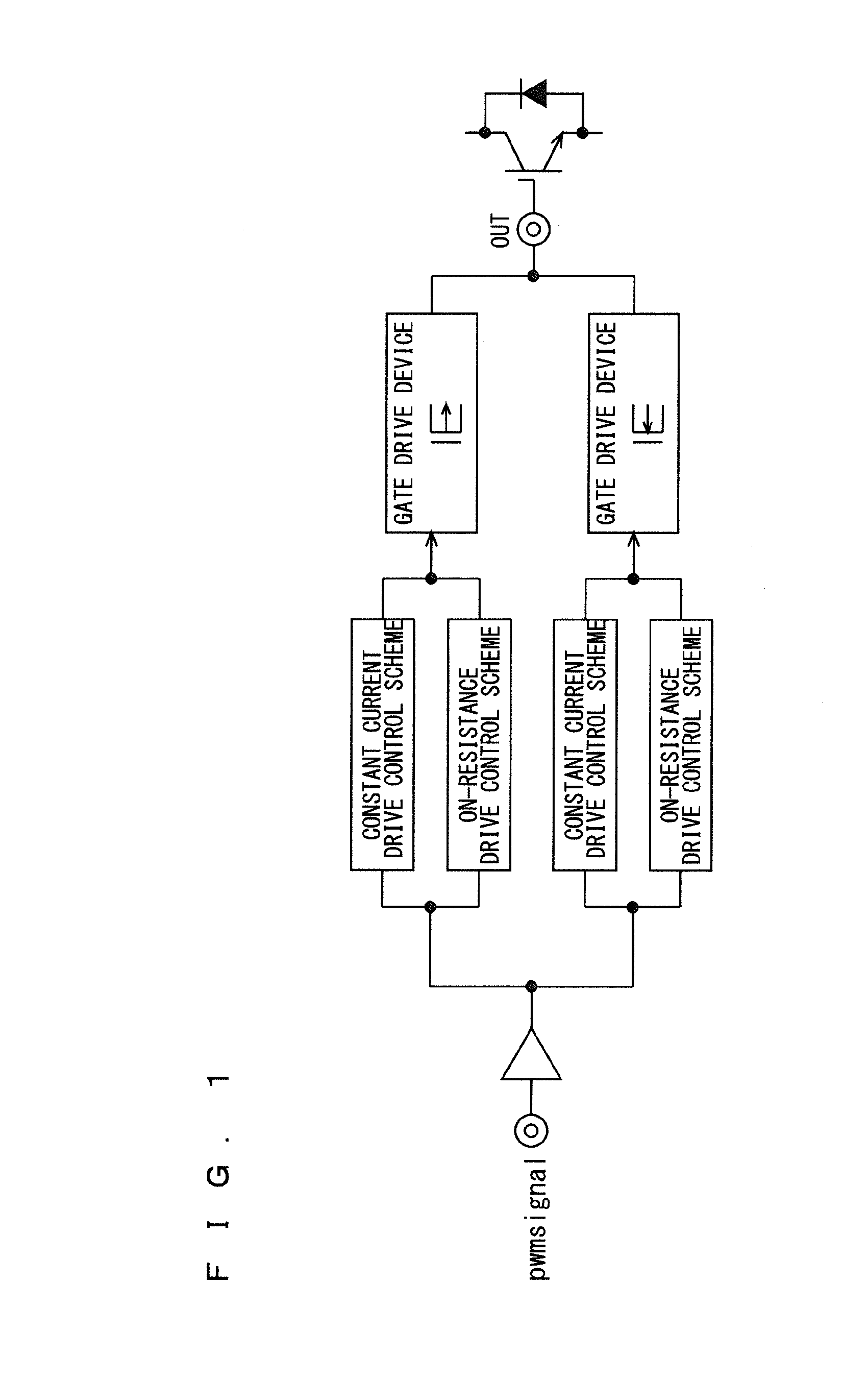
[0022]FIG. 1 is a block diagram illustrating a configuration of a drive circuit 101 according to a first preferred embodiment of the present invention. The drive circuit includes, as a gate drive device, a P-channel MOSFET 1 to perform source control and an N-channel MOSFET 2 to perform sink control. Each of the P-channel MOSFET 1 and the N-channel MOSFET 2 has a constant current drive control scheme and an on-resistance drive control scheme. That is, a single MOSFET is configured to be used for both constant current drive and on-resistance drive.

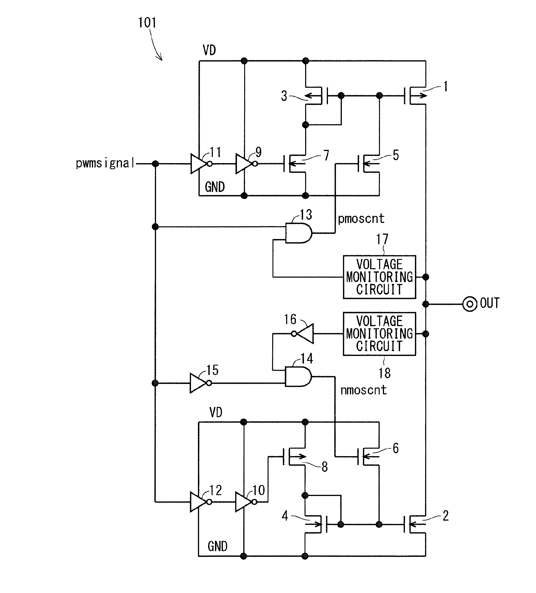
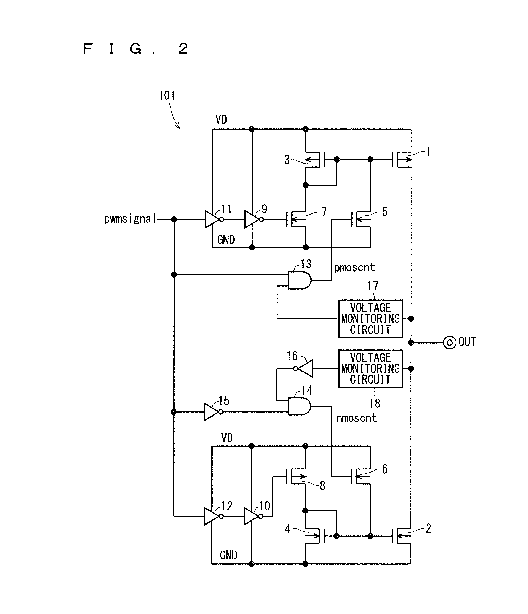
[0023]FIG. 2 is a circuit diagram of the drive circuit 101. The drive circuit 101 drives a switching device connected to an output terminal “out” in response to a control signal “pwmsignal”. The drive circuit 101 includes a source-side circuit and a sink-side circuit, and the configuration of the sink-side circuit is symmetrical to that of the source-side circuit, being provided with opposing polarity. Acc...


PUM


Abstract

A drive circuit of the present invention, which drives a switching device in response to a control signal, includes: a current mirror circuit including an output transistor connected to a control electrode of the switching device and a reference transistor that is connected to the output transistor in a current mirror manner and supplies a mirror current to the output transistor; and a potential change circuit that is connected to the reference transistor and changes a control potential of the output transistor from a potential during mirror operation of the current mirror circuit.

Description

BACKGROUND OF THE INVENTION[0001]1. Field of the Invention[0002]The present invention relates to gate drive control for driving a switching device.[0003]2. Description of the Background Art[0004]A switching device has two drive modes: on-resistance drive and constant current drive. The on-resistance drive mode causes a large drive current to flow at the initial time of gate driving so that the occurrence of Electro-Magnetic Interference (EMI) noise poses a problem.[0005]On the other hand, while the constant current drive mode reduces the EMI noise at the initial phase of gate driving, there is a problem that the constant current drive mode requires a very large device size compared with the on-resistance drive mode.[0006]As such, Japanese Patent Application Laid-Open No. 2009-11049 proposes a drive circuit that uses both the constant current drive and on-resistance drive modes and switches between them in use as needed.SUMMARY OF THE INVENTION[0007]An object of the present invention...

Claims


Application Information

Patent Timeline
Patent Type & Authority Applications(United States)
IPC IPC(8): G05F1/59
CPCG05F1/59
Inventor IMANISHI, MOTOKISAKAI, KENJINAKASHIMA, TAKAKI
Owner MITSUBISHI ELECTRIC CORP
Why Eureka
Try Eureka