Supercharge Your Innovation With Domain-Expert AI Agents!

Communication system

a communication system and communication technology, applied in the field of communication systems, can solve the problems of lower throughput than can be achieved by type 1a and type 1b rns

Active Publication Date: 2015-07-09
NEC CORP
View PDF11 Cites 13 Cited by
  • Summary
  • Abstract
  • Description
  • Claims
  • Application Information

AI Technical Summary

Benefits of technology

The present invention aims to improve communication systems and components to address issues encountered in previous generations. The technical effects of the patent are to offer an enhanced communication system and components that address issues that previously existed.

Problems solved by technology

Type 1 RNs must share bandwidth between RN-Uu and RN-Un and this may result in lower throughput than can be achieved by Type 1a and Type 1b RNs.

Method used


Image

  • Communication system
  • Communication system
  • Communication system

Examples


Embodiment Construction

Overview

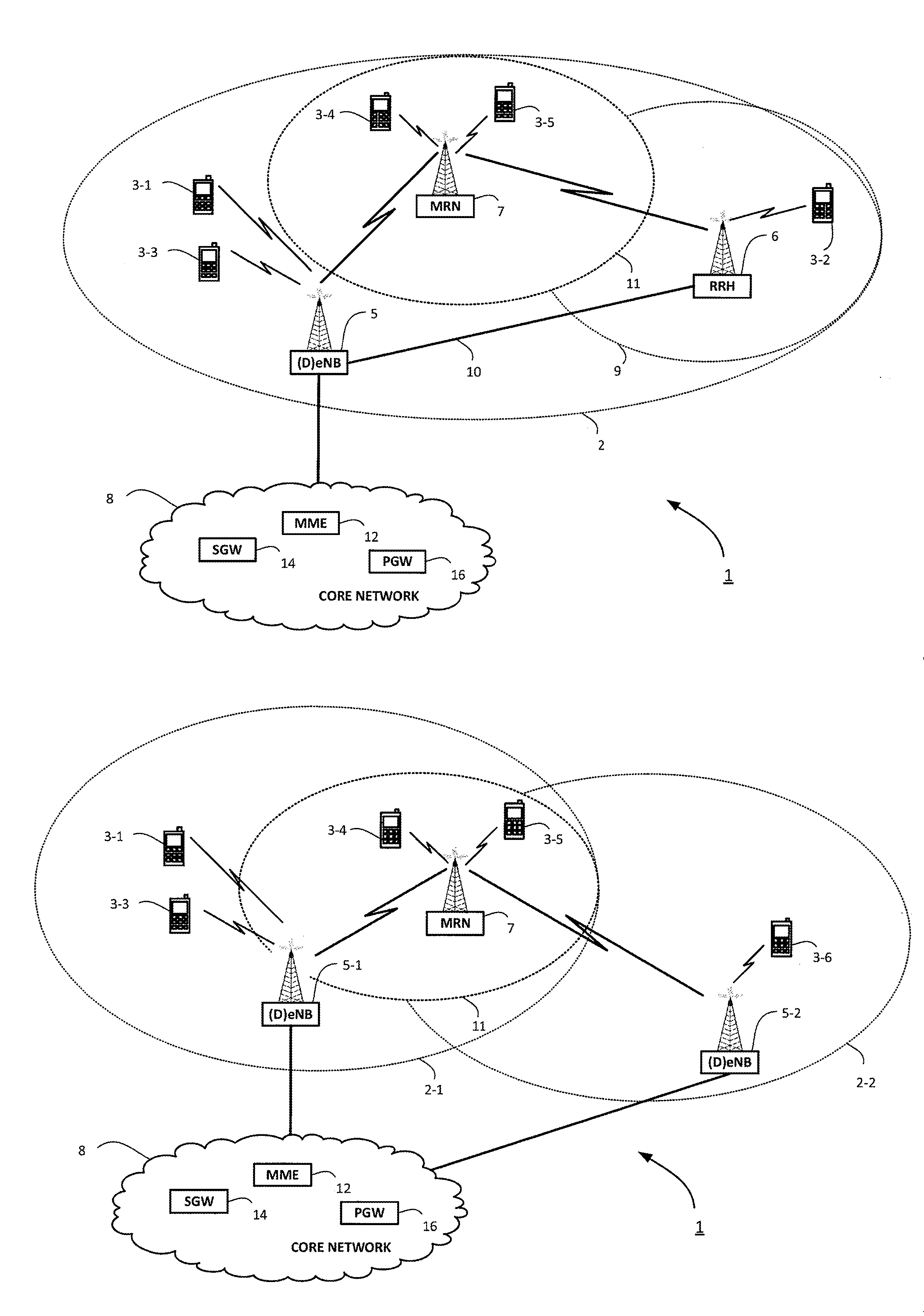
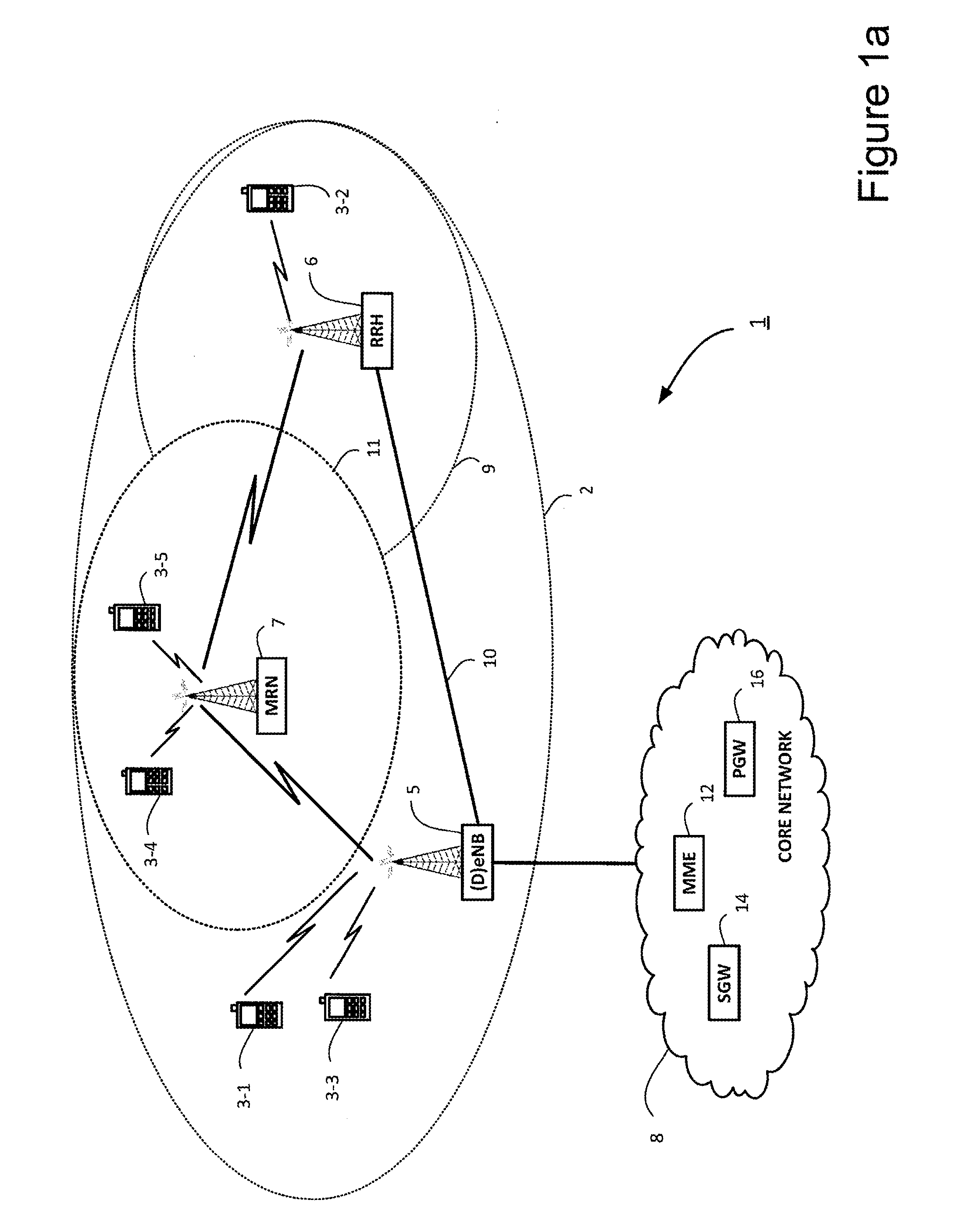
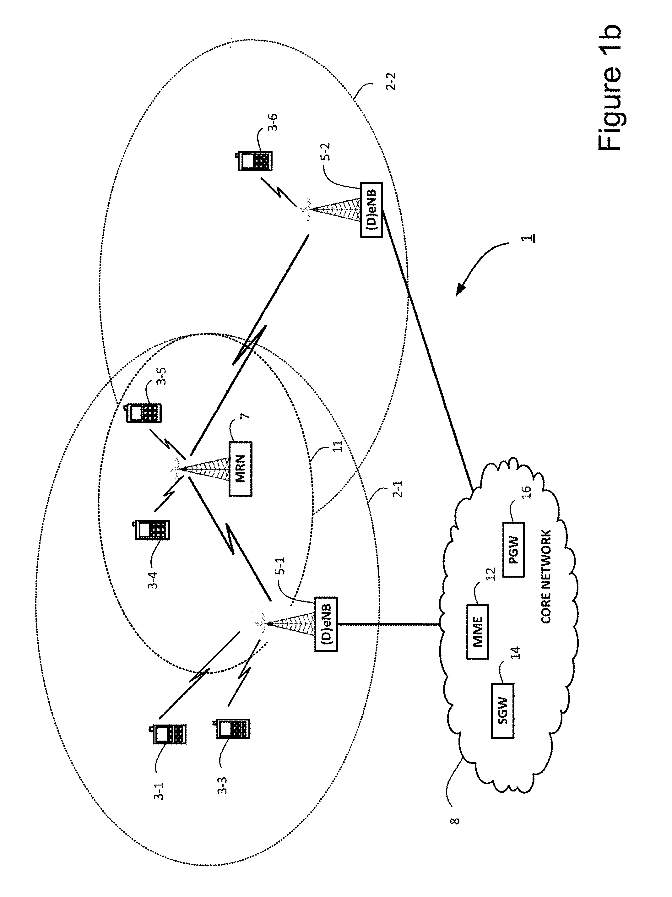
[0034]FIG. 1a schematically illustrates a mobile (cellular) telecommunication system 1 including user equipment (UE) 3, comprising a plurality of mobile telephones 3-1 to 3-5, that are served in a macro cell 2 of a donor base station 5. The telecommunication system 1 also comprises a Remote Radio Head (RRH) 6, a relay node 7 and a core network 8. The RRH 6 is connected directly to the donor base station 5 by a high speed, high bandwidth communication link 10, such as an optical fiber link, through which the RRH 6 sends signals to and receives signals from the donor base station 5. Although one RRH 6 is shown in FIG. 1a, multiple may be provided if desired. The RRH 6 is controlled and synchronised by the donor base station 5 such that it transmits, over the air interface, signals to mobile telephones (in this case telephone 3-2) located within its cell 9 and receives signals back from those mobile telephones. In this exemplary embodiment, the RRH 6 is a low power transmitter ...


PUM


Abstract

The invention provides a relay node that can relay received data to one or more communications devices served by the relay node. The relay node has transceiver circuitry that transmits signals to and that receives signals from one or more remote transmission points and the one or more communications devices served by the relay node; and a communications control module for controlling the operation of the relay node such that in a first operating state the relay node is configured to receive data to be relayed, from a remote transmission point and such that in a second operating state the relay station is configured to receive data to be relayed, from a plurality of remote and separate transmission points.

Description

TECHNICAL FIELD[0001]The present invention relates to a communication system and to components thereof for providing communication services to mobile or fixed communication devices. The invention has particular but not exclusive relevance to providing improved communication links to relay nodes (RNs) in Long Term Evolution (LTE) communication systems currently being developed by the 3rd Generation Partnership Project (3GPP).BACKGROUND ART[0002]Relay nodes were introduced in Rel-10 of the 3GPP standards documentation to provide coverage extension within the cell operated by a base station (eNB), as a tool to improve, for example, the coverage of high data rates for User Equipment (UE), temporary network deployment, cell edge throughput and / or to provide coverage in new cell areas. Mobile RNs (MRNs) are also included in Rel-11 as a study item and the deployment use case is limited to high speed trains where the relay node in mounted on and moves with the train. The LTE specifications ...

Claims


Application Information

Patent Timeline
Patent Type & Authority Applications(United States)
IPC IPC(8): H04B7/155
CPCH04B7/15557H04W88/04H04B7/15507H04B7/15592
Inventor SHARMA, VIVEKAWAD, YASSIN ADEN
Owner NEC CORP
Features
  • R&D
  • Intellectual Property
  • Life Sciences
  • Materials
  • Tech Scout
  • Unparalleled Data Quality
  • Higher Quality Content
  • 60% Fewer Hallucinations
Learn More