Apparatus for blow molding glass bottle, and molding method therefor

a glass bottle and glass bottle technology, applied in glass tempering apparatuses, blowing machines, manufacturing tools, etc., can solve the problems of inconvenient use, waste, and inability to use remaining contents

Active Publication Date: 2015-07-16
PACIFIC GLAS
View PDF8 Cites 3 Cited by
  • Summary
  • Abstract
  • Description
  • Claims
  • Application Information

AI Technical Summary

Benefits of technology

[0015]The present invention provides a glass bottle in which a groove is formed at the center of the inner bottom surface of the glass bottle and, when a dispenser such as a discharging pump is used, a discharge tube disposed in the dispenser is located at the groove, so that all of contents in the glass bottle can be discharged.

Problems solved by technology

However, if the contents are discharged and the water level of the contents is close to the bottom, a discharge tube for discharging contents is not functioned well in a state in which the contents are entirely dispersed on the horizontal surface, and a predetermined amount of the contents is not discharged, so that use thereof is inconvenient, and the remaining contents cannot be used and is wasted.

Method used


Image

  • Apparatus for blow molding glass bottle, and molding method therefor
  • Apparatus for blow molding glass bottle, and molding method therefor
  • Apparatus for blow molding glass bottle, and molding method therefor

Examples


Embodiment Construction

[0026]Hereinafter, the present invention will be described in detail with reference to the accompanying drawings.

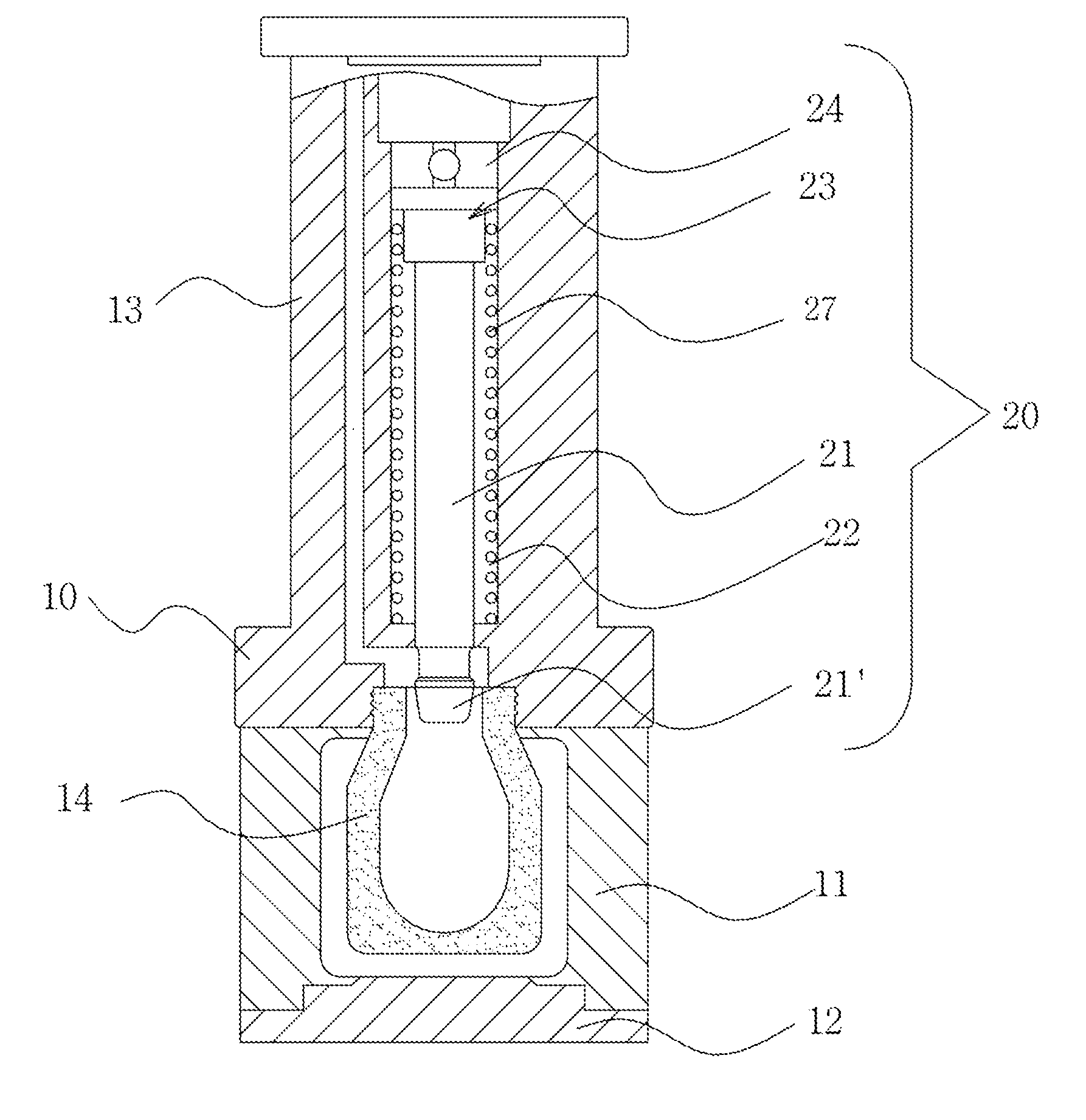
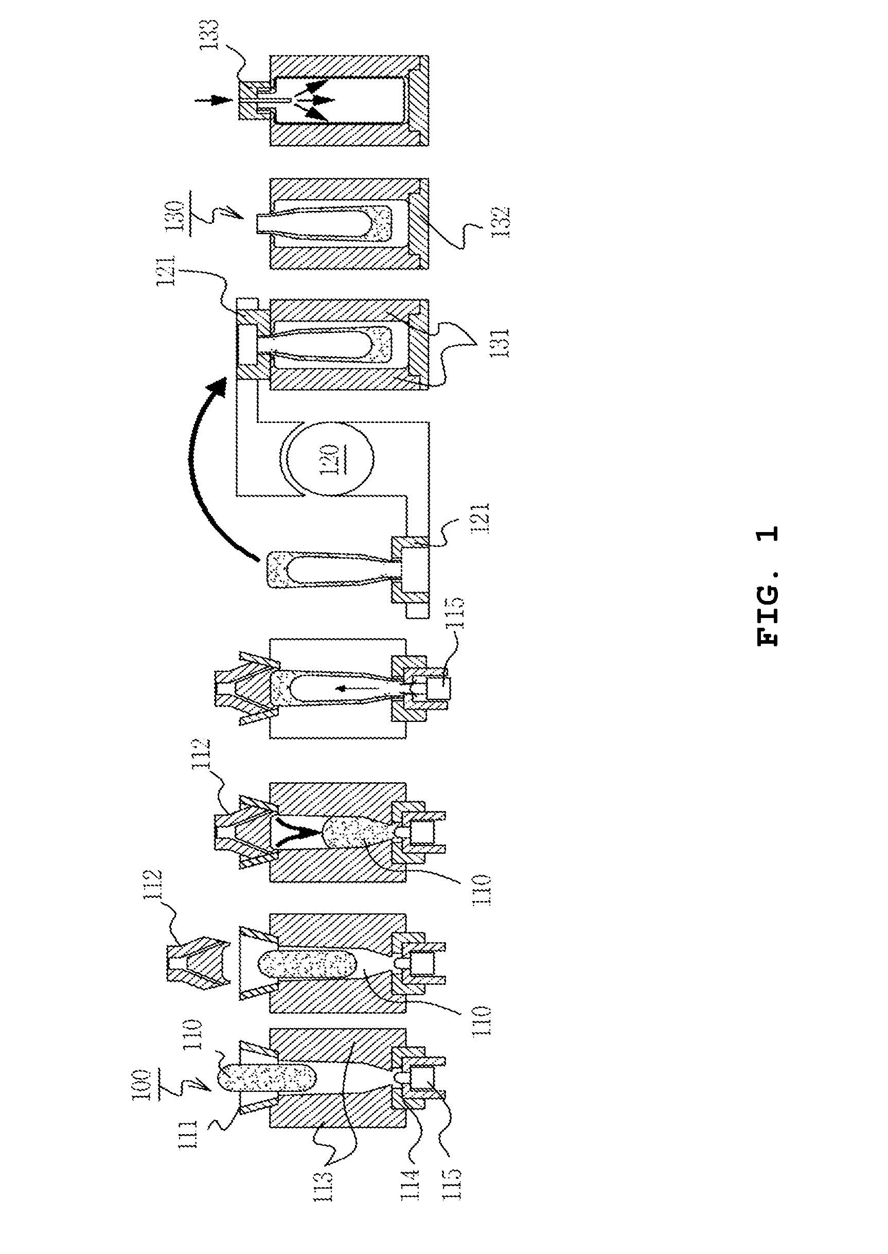
[0027]First, as illustrated in FIG. 4, a method of blow-molding a glass bottle by a blow mold 10 according to the present invention includes: a glass bottle molding preparing step (S1) before secondly molding a base mold 12 disposed at the lower side of a pair of tubular mold bodies 11 and a firstly molded glass bottle 14; a glass bottle molding step (S2) in which a blow head 13 is positioned on the mold bodies 11, and when molding air is injected, the first glass bottle 14 comes into contact with the inner wall of the mold bodies 11 and the base mold 12 so as to be molded into a second glass bottle; a piston rod lowering step (S3) of lowering a piston rod 21 of a groove molder 20 disposed at an inner peripheral portion of the blow head 13; a groove forming step (S4) of forming a groove portion 15 on an inner bottom surface of the glass bottle 14 by lowering the piston ro...


PUM

PropertyMeasurementUnit
elasticaaaaaaaaaa
shapeaaaaaaaaaa
timeaaaaaaaaaa

Abstract

The present invention relates to an apparatus for blow-molding a glass bottle, and more particularly, to an apparatus for blow-molding a glass bottle in which molding air is injected into a pair of mold bodies such that molten glass accommodated in the mold bodies is formed into a glass bottle and a groove is formed at the center of the inner side of the bottom surface of the glass bottle. The apparatus for blow-molding a glass bottle of the present invention uses a blow mold (10) configured to include: a pair of mold bodies (11) forming a tubular body; a base mold (12) which molds the bottom surface of the glass bottle; and a blowing head (13) which are arranged in the upper portions of the mold bodies (11) and into which molding air is injected such that the glass bottle is expanded after primary molding and closely contacts the inner walls of the mold bodies (11) and the base mold (12). A groove molder (20) is provided on the inner circumferential edge portion of the blowing head (13) such that a groove portion (15) can be molded on the inner side of the bottom surface of the glass bottle (14).

Description

TECHNICAL FIELD[0001]The present invention relates to an apparatus for blow-molding a glass bottle and a method for molding the same and, more particularly, to an apparatus for blow-molding a glass bottle and a method for molding the same, which injects molding air into a pair of molding bodies to mold a glass bottle from molten glass received inside the molding bodies, and forms a groove at the center of the inner bottom surface of the glass bottle using a groove molder.Background Art[0002]In general, methods for molding a glass bottle are largely classified into the blow molding method, the pressing molding method, and the casing molding method, and the above-mentioned methods manufacture a glass bottle by injecting glass gob into a mold.[0003]The blow molding method is one of the glass molding methods which are mainly used for manufacturing a glass bottle. Before an apparatus for molding a glass bottle using the blow molding method is described, not a specific glass bottle but a ...

Claims


Application Information

Patent Timeline
Patent Type & Authority Applications(United States)
IPC IPC(8): C03B9/14C03B9/36C03B9/335
CPCC03B9/145C03B9/3681C03B9/335C03B9/165C03B9/32C03B9/36C03B9/3618C03B9/3636C03B9/3663C03B9/14C03B9/30
Inventor HWANG, JAEYEON
Owner PACIFIC GLAS
Why Eureka
Try Eureka