Method to improve blowthrough via split exhaust

a split exhaust and blower technology, applied in the direction of machines/engines, output power, electric control, etc., can solve the problems of reducing fuel economy, limiting maximum torque, engine knocking, etc., to reduce fuel economy, increase engine power density, and limit maximum torque

Inactive Publication Date: 2015-07-16
FORD GLOBAL TECH LLC
View PDF4 Cites 16 Cited by
  • Summary
  • Abstract
  • Description
  • Claims
  • Application Information

AI Technical Summary

Benefits of technology

[0006]The inventors herein have recognized the above issues and identified approaches to at least partly address the issues. In one example approach, a method for a turbocharged engine with a split exhaust manifold system is provided. The method comprises flowing exhaust through a first exhaust valve to a turbine of the turbocharger, flowing exhaust via a second exhaust valve to upstream of an emission control device and flowing low pressure EGR and blowthrough air via a third valve to upstream of a turbo-compressor into the compressor inlet within a common engine cycle combustion event. By using appropriate valve timing controls, a combination of EGR and blowthrough air techniques can be used to reduce combustion temperatures and thus, mitigate engine knock.
[0008]In this way, knock can be reduced by combining blowthrough and EGR in one flow path. By allowing fresh intake air to blow through any residual hot exhaust gases in the cylinder clearance volume, the combustion chamber may be cooled. The mix of exhaust gases and blowthrough air exiting the chamber may be combined with additional fresh air at the compressor, cooled in a charge air cooler (CAC) and eventually recirculated in the engine as EGR to further reduce knock. By using the CAC to cool the residual exhaust gases along with fresh compressed air, a separate EGR cooler may not be required. Further, the EGR throttle may be dispensed with by coupling the compressor inlet valve to the compressor, whereby the mix of exhaust and blowthrough air is drawn into the low pressure inlet of the compressor through the cylinder from a high pressure intake manifold. Since blowthrough air and residual exhaust gases are directed to a compressor inlet at lower pressure, blowthrough may be possible over a greater range of engine speeds. Additionally, exhaust pumping losses encountered in a traditional design, where all exhaust flows into a high pressure turbine inlet, may be reduced. Moreover, since the blowthrough air is not directed to an emission control device, maintaining stoichiometric ratio in the exhaust with an injection of extra fuel may not be required. Overall, a turbocharged engine can be operated with less spark retard from maximum torque.

Problems solved by technology

However, engine knock may occur due to increased combustion temperatures.
The engine knock may be addressed by retarding spark timing; however, significant spark retard can reduce fuel economy and limit maximum torque.
Knock is especially problematic under boosted conditions due to high charge temperatures.
The inventors herein have identified potential issues, including issues with the above approaches to addressing knock limits.
Further, a separate EGR cooler may be used to cool the hot exhaust gases before they can be supplied to the intake manifold, thus increasing system costs and requiring packaging space.
Further still, in the example where a blowthrough technique is used to reduce knock, additional fuel injected to bring exhaust gases to a stoichiometric ratio can cause over-temperature of the catalyst and affect emissions while increasing fuel consumption.
An additional limitation of the blowthrough technique is its restricted use for low engine speeds when compressor outlet pressure is higher than pre-turbine exhaust pressure.

Method used


Image

  • Method to improve blowthrough via split exhaust
  • Method to improve blowthrough via split exhaust
  • Method to improve blowthrough via split exhaust

Examples


Embodiment Construction

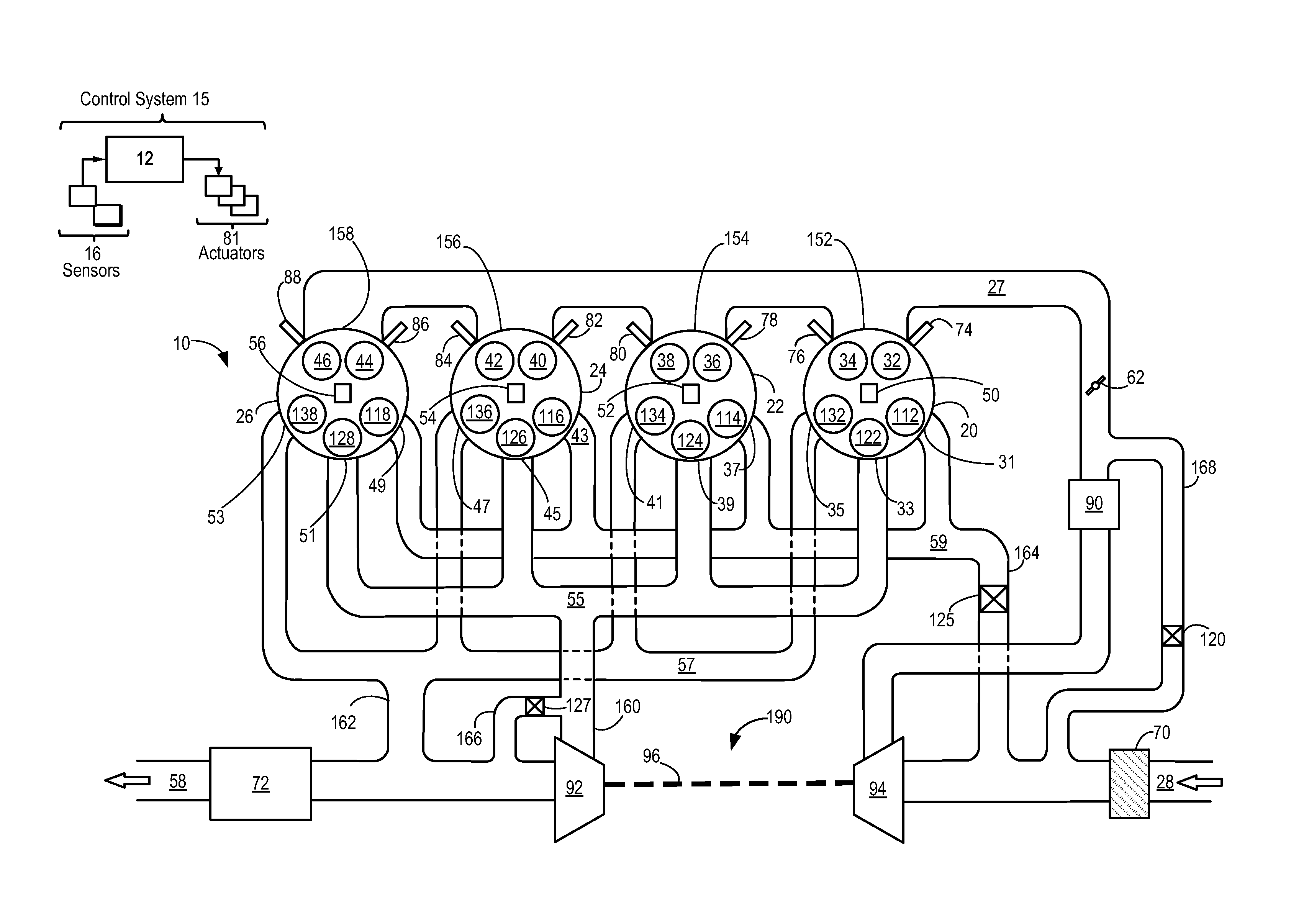
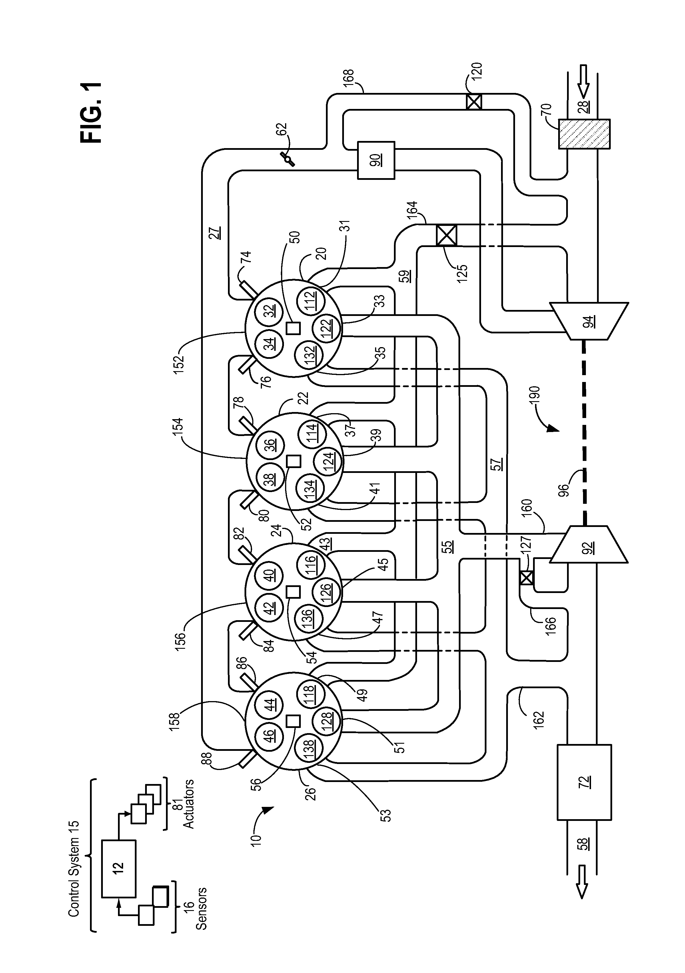
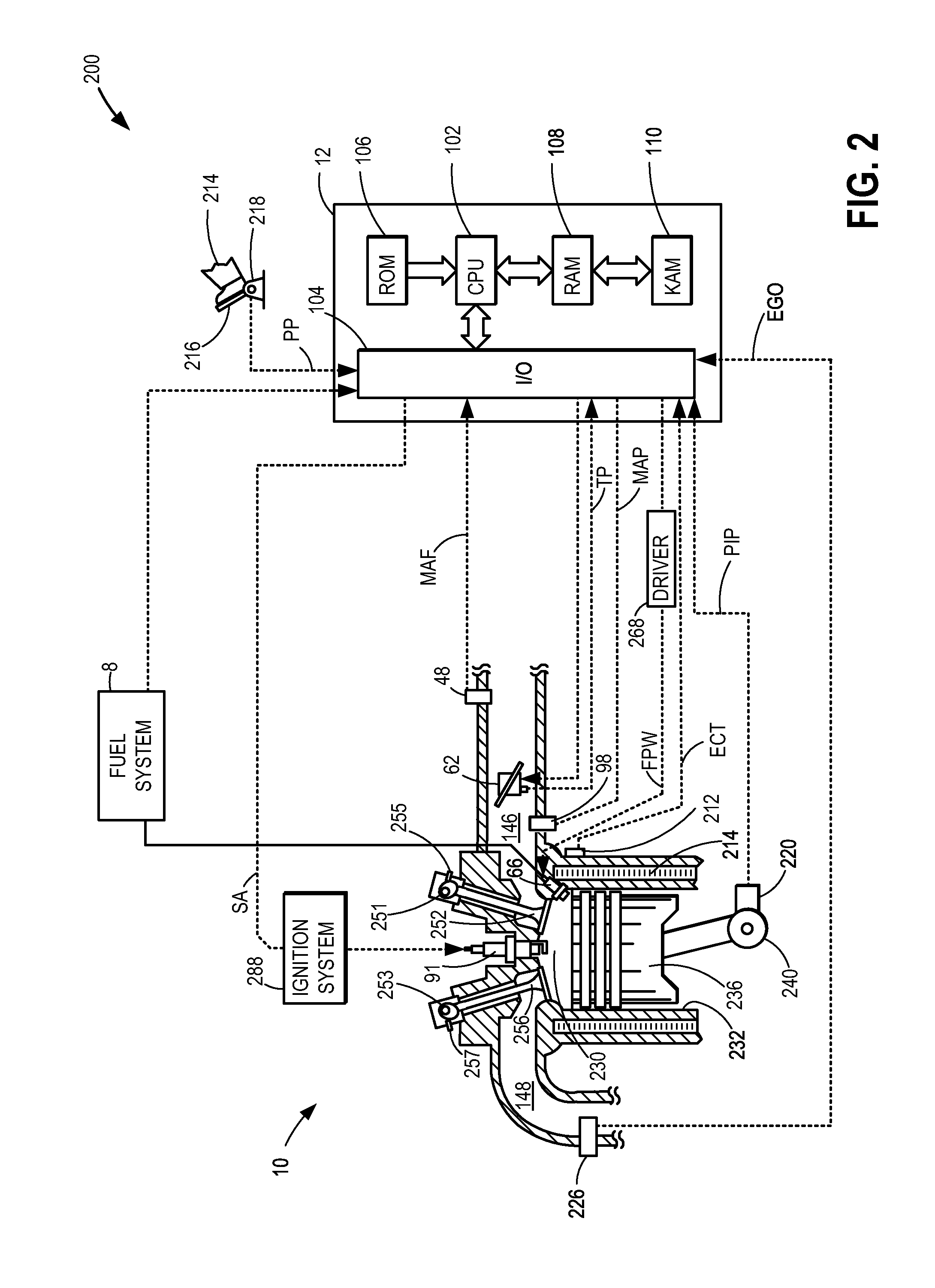
[0015]The following description relates to systems and methods for controlling knock in an engine, such as the engine system of FIGS. 1-2, by exhausting an engine cylinder through three distinct passages. Specifically, within one combustion cycle, a first or blowdown portion of an exhaust may be guided to a turbine of a turbocharger through a first passage, a second or scavenged portion of an exhaust may be directed to an emission control device via a second passage while a third portion of exhaust gases towards the end of an exhaust stroke mixed with blowthrough air may be directed to an inlet of a compressor in a turbocharger through a third passage. Each cylinder of the engine, thus, may comprise five valves: two intake valves, two exhaust valves and one compressor inlet valve. An engine controller may be configured to perform a control routine, such as the routine of FIG. 4, to operate the compressor inlet valve based on a variety of engine operating conditions such as those sho...


PUM


Abstract

Methods and systems are provided for a boosted engine having a split exhaust system. One method includes reducing knock by flowing a combination of exhaust from towards the end of an exhaust stroke and blowthrough air to the intake of a compressor via a compressor inlet valve.

Description

TECHNICAL FIELD[0001]The present application relates to a split exhaust in an exhaust system of a boosted internal combustion engine.BACKGROUND AND SUMMARY[0002]Engines may use boosting devices, such as turbochargers, to increase engine power density. However, engine knock may occur due to increased combustion temperatures. The engine knock may be addressed by retarding spark timing; however, significant spark retard can reduce fuel economy and limit maximum torque. Knock is especially problematic under boosted conditions due to high charge temperatures.[0003]One method to reduce charge temperature and therefore knock, is via blowthrough wherein boosted intake air is blown through the combustion chamber to the exhaust during a positive valve overlap phase.[0004]Another method to suppress knock is by diluting intake air with cooled exhaust gas recirculation (EGR). An example approach of controlling the flow of exhaust gases for EGR is shown by Roth (U.S. Pat. No. 8,495,992) wherein a...

Claims


Application Information

Patent Timeline
Patent Type & Authority Applications(United States)
IPC IPC(8): F02D13/02F02M25/07
CPCF02M25/0709F02D13/0242F02B37/02F02D13/0203F02D13/0261F01N13/107F02D41/006F02D41/008F02D41/062F02D41/064F02D41/123F02D41/0055F02D2041/001F02D35/027F02M26/04F02M26/43F02D41/0007F02B37/18Y02T10/12Y02T10/40F02M26/05F02B27/04F02B47/08F02D13/0249F02D13/0257F02D23/00F02F1/4214
Inventor ULREY, JOSEPH NORMANBOYER, BRAD ALAN
Owner FORD GLOBAL TECH LLC
Why Eureka
Try Eureka