
Systems and methods for determining the integrity of a vehicle fuel system

a vehicle fuel system and integrity technology, applied in the direction of machines/engines, electric control, combustion air/fuel air treatment, etc., can solve the problem that the elcm cannot detect leaks larger than the reference orifice, the vehicle engine may not run frequently, and the vacuum generated is not enough, so as to reduce the bleed emission and avoid the effect of increasing production costs

Active Publication Date: 2015-07-16
FORD GLOBAL TECH LLC
View PDF9 Cites 36 Cited by
  • Summary
  • Abstract
  • Description
  • Claims
  • Application Information

AI Technical Summary

Benefits of technology

The patent text describes a system and method for detecting leaks in a vehicle's fuel system using an evaporative leak check module (ELCM) with a single reference orifice. The system includes a fuel tank, fuel vapor canister, and ELCM. The ELCM uses a vacuum to apply a negative pressure to the fuel system and detect leaks based on the resulting pressure. The system can also purge stored fuel vapor from the canister to the fuel tank, reducing bleed emissions. The technical effects of the patent text include improving the efficiency of the ELCM by using a reference orifice with a higher vacuum threshold, and allowing vehicles to meet future emissions standards without costly upgrades to the ELCM.

Problems solved by technology

In some vehicles, such as hybrid electric vehicles, the vehicle engine may not run frequently, or may not generate enough vacuum to conduct a leak test.
However, this limits the ELCM to detecting leaks larger than the reference orifice.
Vehicles built with ELCM reference orifices of 0.02″ are inadequate for determining leaks of 0.01″ in this way.
It would require costly service to replace the ELCM in these vehicles.
However, the vehicles most likely to comprise an ELCM (HEVs, PHEVs, low intake vacuum vehicles) are likely to have limited opportunities to purge the canister.
In order to remove the stored vapor, the engine may have to be forced on, decreasing the vehicle efficiency.
If the ELCM test is performed after a vehicle-off condition, the vapor canister could remain full over a long period of time, leaving the canister susceptible to bleed emissions.

Method used


Image

  • Systems and methods for determining the integrity of a vehicle fuel system
  • Systems and methods for determining the integrity of a vehicle fuel system
  • Systems and methods for determining the integrity of a vehicle fuel system

Examples


Embodiment Construction

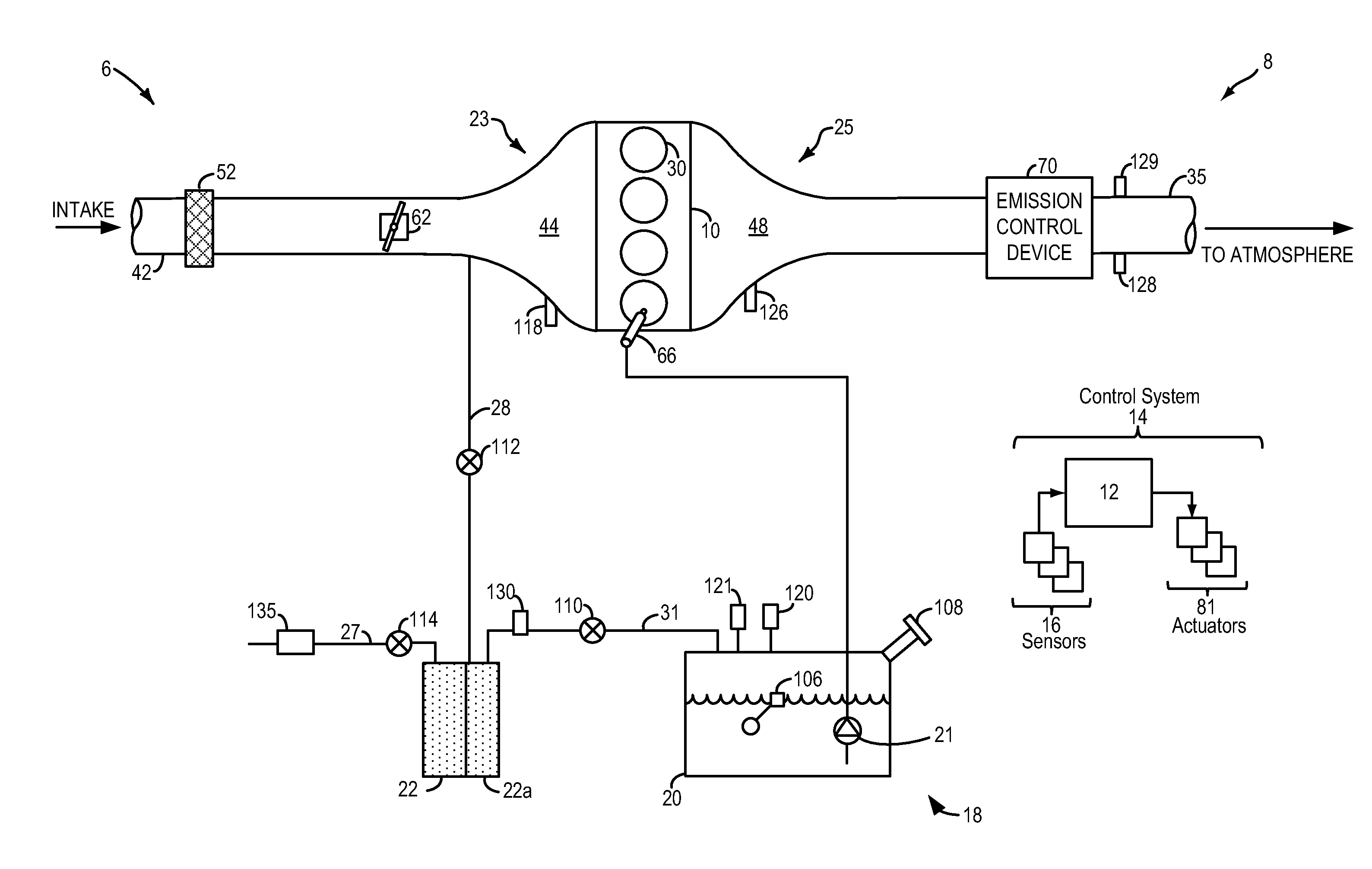
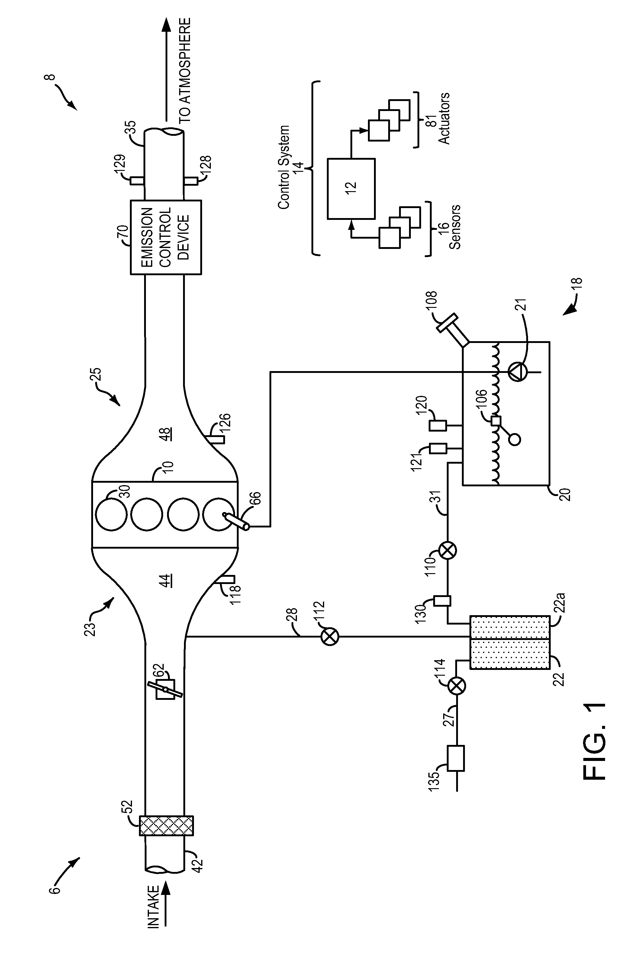
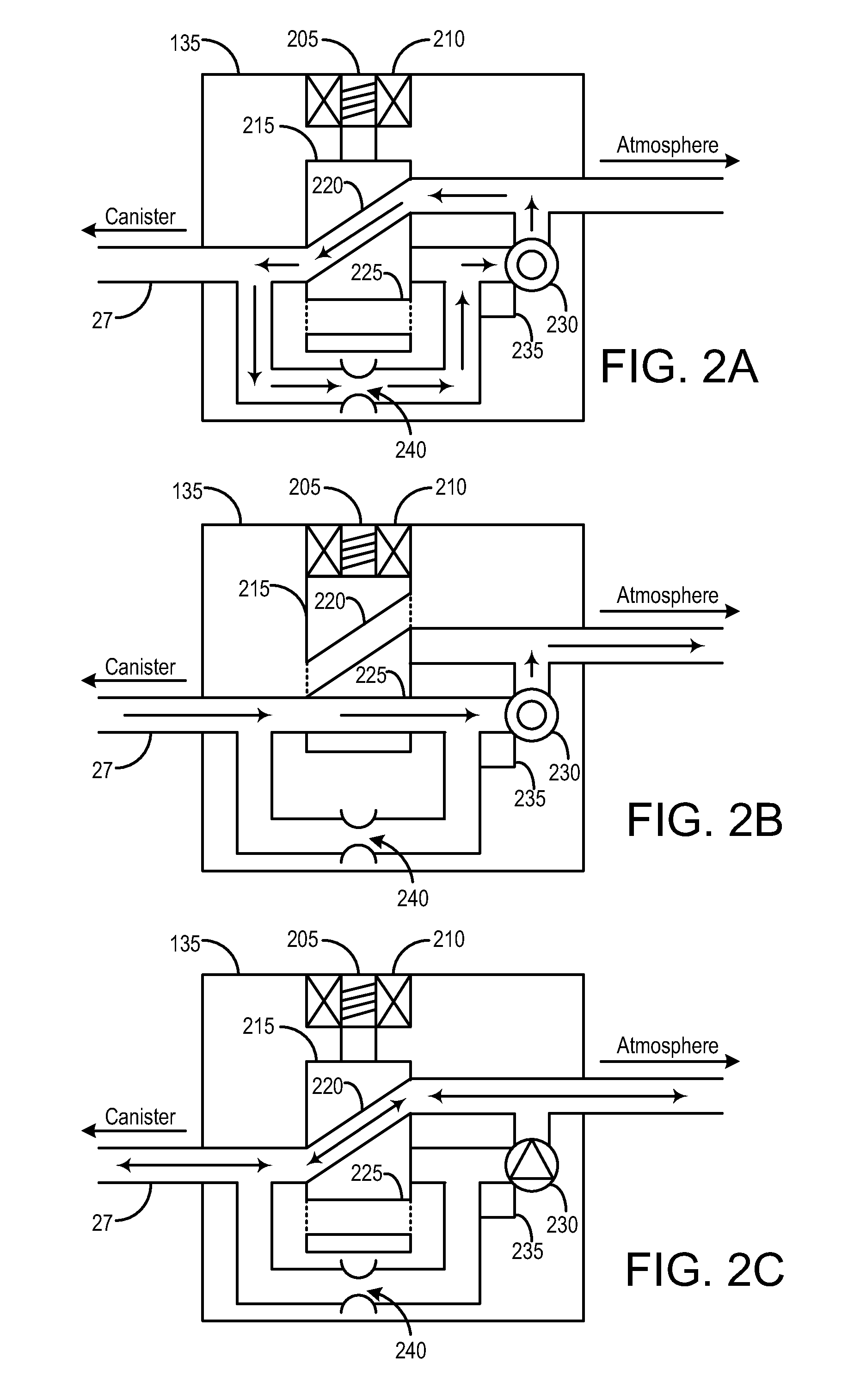
[0018]This description relates to systems and methods for leak testing a fuel system coupled to an engine, such as the fuel system and engine system depicted in FIG. 1. The fuel system and engine system may be included in a hybrid vehicle, and may necessitate the inclusion of an evaporative leak check module (ELCM). An ELCM may be configured to adapt conformations, such as the conformations shown in FIGS. 2A-2C. A controller or power train control module (PCM) may be configured to perform a control routine for an ELCM test, such as the method depicted in FIG. 3. The method may include determining the integrity of the canister side of the fuel system first, followed by determining the integrity of the fuel tank by drawing a vacuum on the fuel tank, sealing the fuel tank, then monitoring the subsequent vacuum bleed-up. FIG. 4 shows an example ELCM test using the method of FIG. 3. FIG. 5 shows an alternative method for determining the integrity of the canister side of the fuel system, ...


PUM


Abstract

A method, comprising: indicating leakage on a canister side of a fuel system based on a first fuel system pressure following applying a vacuum to the fuel system with a fuel tank isolation valve closed; and indicating leakage on a fuel tank side of the fuel system based on the first fuel system pressure and a second fuel system pressure following applying a vacuum to the fuel system with the fuel tank isolation valve open. In this way, an ELCM with a single reference orifice may be used to perform a leak test with two different thresholds for leak detection. This may allow vehicles currently in production to meet future emissions standards without costly upgrades to the ELCM.

Description

BACKGROUND AND SUMMARY[0001]Vehicle emission control systems may be configured to store fuel vapors from fuel tank refueling and diurnal engine operations, and then purge the stored vapors during a subsequent engine operation. In an effort to meet stringent federal emissions regulations, emission control systems may need to be intermittently diagnosed for the presence of leaks that could release fuel vapors to the atmosphere. In a typical leak test, a vacuum is applied to the fuel system. The integrity of the system is determined by monitoring the decay of the applied vacuum or by comparing the resulting fuel system pressure to an expected pressure. The vacuum source may be the intake manifold of the vehicle engine. In some vehicles, such as hybrid electric vehicles, the vehicle engine may not run frequently, or may not generate enough vacuum to conduct a leak test. Such vehicles are required to have an evaporative leak check module (ELCM) coupled to the fuel system. The ELCM includ...

Claims


Application Information

Patent Timeline
IPC IPC(8): F02M25/08
CPCF02M25/0854B60K15/03504F02D41/22F02D2041/225F02M25/0809
Inventor PEARCE, RUSSELL RANDALLPETERS, MARK W.DUDAR, AED M.YANG, DENNIS SEUNG-MAN
Owner FORD GLOBAL TECH LLC
Features
  • Generate Ideas
  • Intellectual Property
  • Life Sciences
  • Materials
  • Tech Scout
  • Unparalleled Data Quality
  • Higher Quality Content
  • 60% Fewer Hallucinations
Learn More