Antenna coupling for sensing and dynamic transmission

a technology of dynamic transmission and antenna coupling, applied in the direction of transmission monitoring, power management, electrical equipment, etc., can solve the problem of reducing the performance of device features in some electronic devices, and achieve the effect of dynamic reduction of the signal strength of the transmitted rf carrier

Active Publication Date: 2015-07-16
MICROSOFT TECH LICENSING LLC
View PDF5 Cites 103 Cited by
  • Summary
  • Abstract
  • Description
  • Claims
  • Application Information

AI Technical Summary

Benefits of technology

[0002]Implementations described and claimed herein address the foregoing by providing a wireless transmission system that adjusts transmission power of a carrier wave responsive to a detected change in signal strength of the carrier wave at a receiver. To satisfy government-imposed RF transmission limitations without significantly compromising

Problems solved by technology

However, reducing RF transmission power can appreciably decre

Method used


Image

  • Antenna coupling for sensing and dynamic transmission
  • Antenna coupling for sensing and dynamic transmission
  • Antenna coupling for sensing and dynamic transmission

Examples


Embodiment Construction

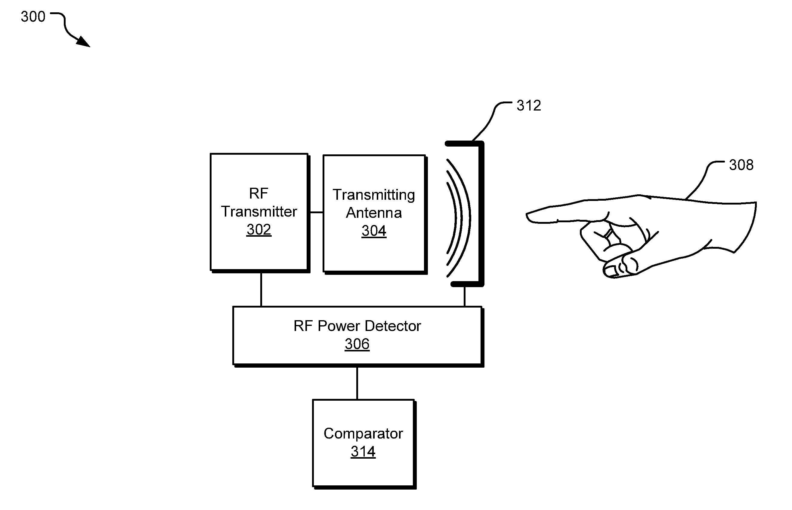
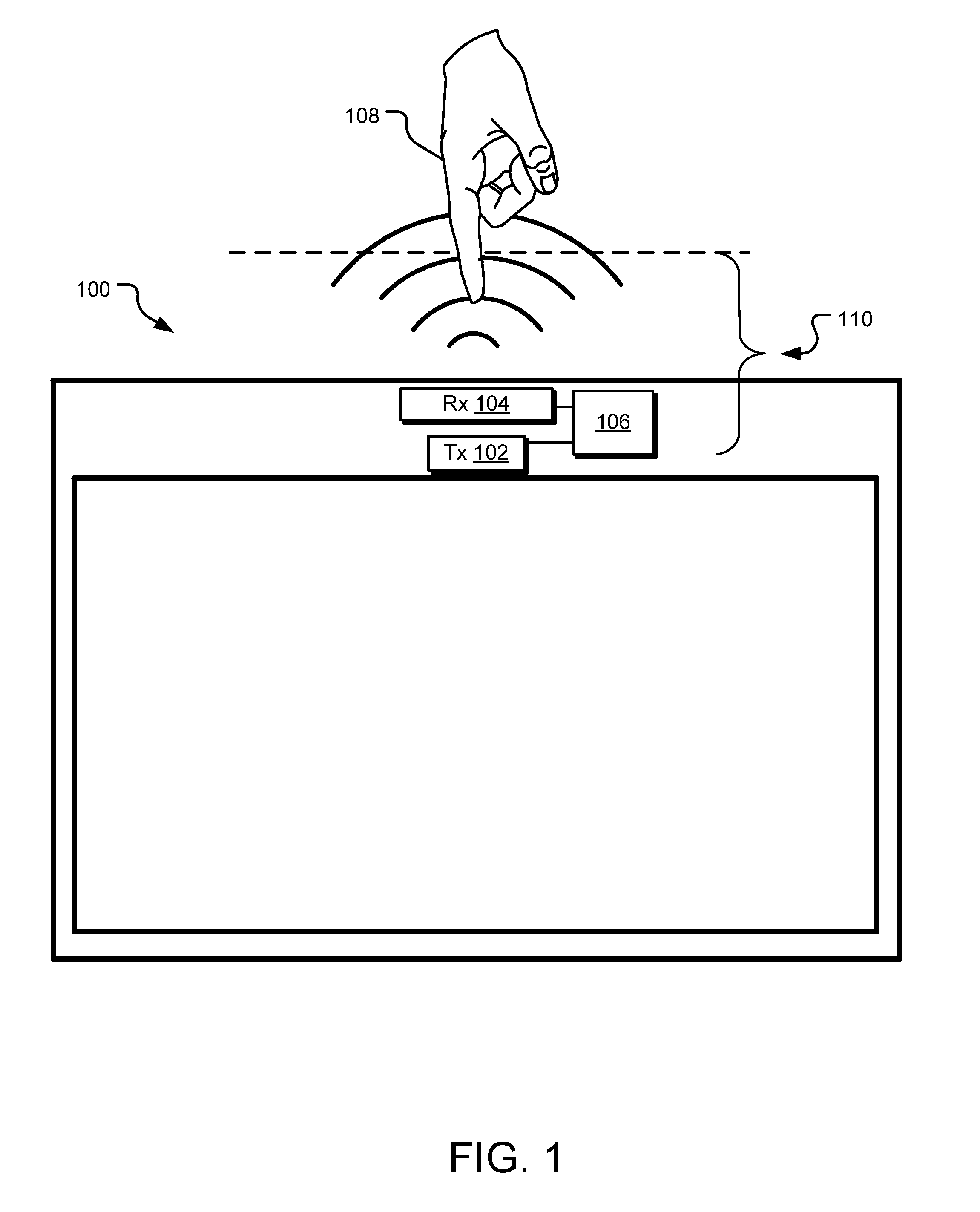
[0009]In some jurisdictions, specific absorption rate (SAR) standards are in place that impose maximum energy absorption limits on electronic device manufacturers. These standards impose restrictions on the amount of electromagnetic radiation that may be emitted at any particular point within a given distance of a transmitting radio frequency (RF) antenna. Particular attention is given to radiation limits at distances within a few centimeters from the device (e.g., 0-3 centimeters), where users are likely to place a human body part near the transmitting antenna. Such restrictions may be satisfied by reducing transmitted carrier signal strength when a dielectric body (e.g., a human body part) is detected in the proximity of the transmitter.

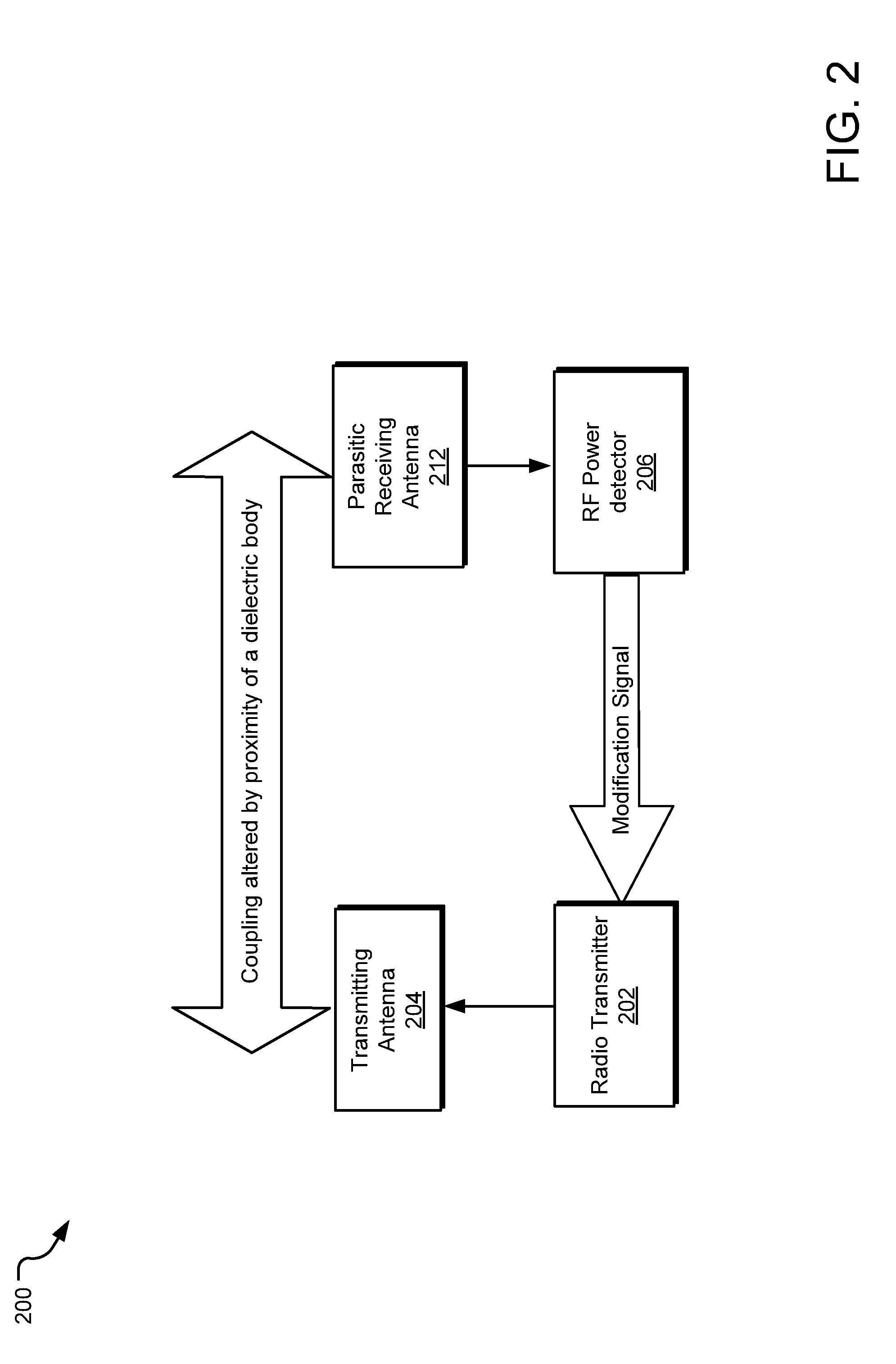
[0010]Implementations of the disclosed technology provide an electronic device that dynamically alters the power of a transmitted carrier wave responsive to detected changes in the signal strength of the carrier wave received at a nearby receiver. ...


PUM


Abstract

A wireless transmission system disclosed herein includes a transmitter-receiver pair. When a dielectric object approaches the transmitter-receiver pair, a signal strength of a transmitted carrier wave increases at the receiver. In response, transmission power of the transmitter can be dynamically reduced. When the dielectric object moves away from the transmitter-receiver pair, a signal strength of the carrier wave decreases at the receiver. In response, the transmission power of the transmitter can be dynamically increased.

Description

BACKGROUND[0001]Consumer electronic devices may be equipped with wireless communication circuitry that makes use of radio frequency (RF) electromagnetic fields. For example, the wireless communications circuitry may transmit and receive RF signals in mobile telephone RF bands, WiFi network RF bands, GPS RF bands, etc. To protect humans from harmful levels of RF radiation when using such devices, government agencies have imposed regulations limiting RF transmission power from some wireless electronic devices, such as tablet computers and mobile phones. However, reducing RF transmission power can appreciably decrease performance of device features in some electronic devices.SUMMARY[0002]Implementations described and claimed herein address the foregoing by providing a wireless transmission system that adjusts transmission power of a carrier wave responsive to a detected change in signal strength of the carrier wave at a receiver. To satisfy government-imposed RF transmission limitation...

Claims


Application Information

Patent Timeline
IPC IPC(8): H04W52/24H04W72/04H04B1/38H04B17/00
CPCH04W52/245H04B1/3838H04W72/0473H04B17/0057H04W52/367H04B17/318H04B17/10
Inventor MERCER, SEAN RUSSELLKHAWAND, CHARBEL
Owner MICROSOFT TECH LICENSING LLC
Why Eureka
Try Eureka