Baking pan insert

a technology for baking pans and inserts, which is applied in the field of baking pan inserts, can solve the problems of inflicting damage to baking pans, imperfect or messy pieces of baked goods, and adhesion to baking implements, and achieves the effects of convenient preparation, protection, transportation and serving

Active Publication Date: 2015-07-23
PANOVATIONS
View PDF0 Cites 20 Cited by
  • Summary
  • Abstract
  • Description
  • Claims
  • Application Information

AI Technical Summary

Benefits of technology

[0006]Embodiments of the baking pan insert may be used with a simple or conventional baking pan having a bottom, side walls and end walls. Alternatively, a baking pan insert be used with a baking pan that is specifically configured to receive the baking pan insert. For example, a custom baking pan may include shelves on opposite side walls of the baking pan that may receive structures on the baking pan insert and aid in guiding the baking pan insert as the baking pan insert is moved along the bottom of the baking pan. The shelves may be offset from an upper rim of the pan such that the pan may accommodate a lid even when the particular embodiment of the baking pan insert possesses a handle, a guide, or other features extending above the side walls of the baking pan insert. Embodiments of such systems may permit a user to easily prepare, protect, transport, and serve a baked good using the baking pan insert.

Problems solved by technology

Baking poses several common frustrations including: adhesion, mess, and damage to the baking implements including the pan.
The first of these frustrations, adhesion, relates to the possibility of the food becoming adhered to the bottom of a pan.
Attempting to remove an adhered baked good from a baking pan with a spatula or other implement can require the application of excessive force, which often results in imperfect or messy pieces of the baked good, and additionally to damage inflicted on the baking pan by the implement.
Furthermore, even in the best case scenario of perfectly baked food, the appearance of the result can be easily ruined by imperfect application of the serving utensil.

Method used


Image

  • Baking pan insert
  • Baking pan insert
  • Baking pan insert

Examples


Embodiment Construction

[0016]In the following description, various embodiments of the present invention will be described. For purposes of explanation, specific configurations and details are set forth in order to provide a thorough understanding of the embodiments. However, it will also be apparent to one skilled in the art that the present invention may be practiced without the specific details. Furthermore, well-known features may be omitted or simplified in order not to obscure the embodiment being described.

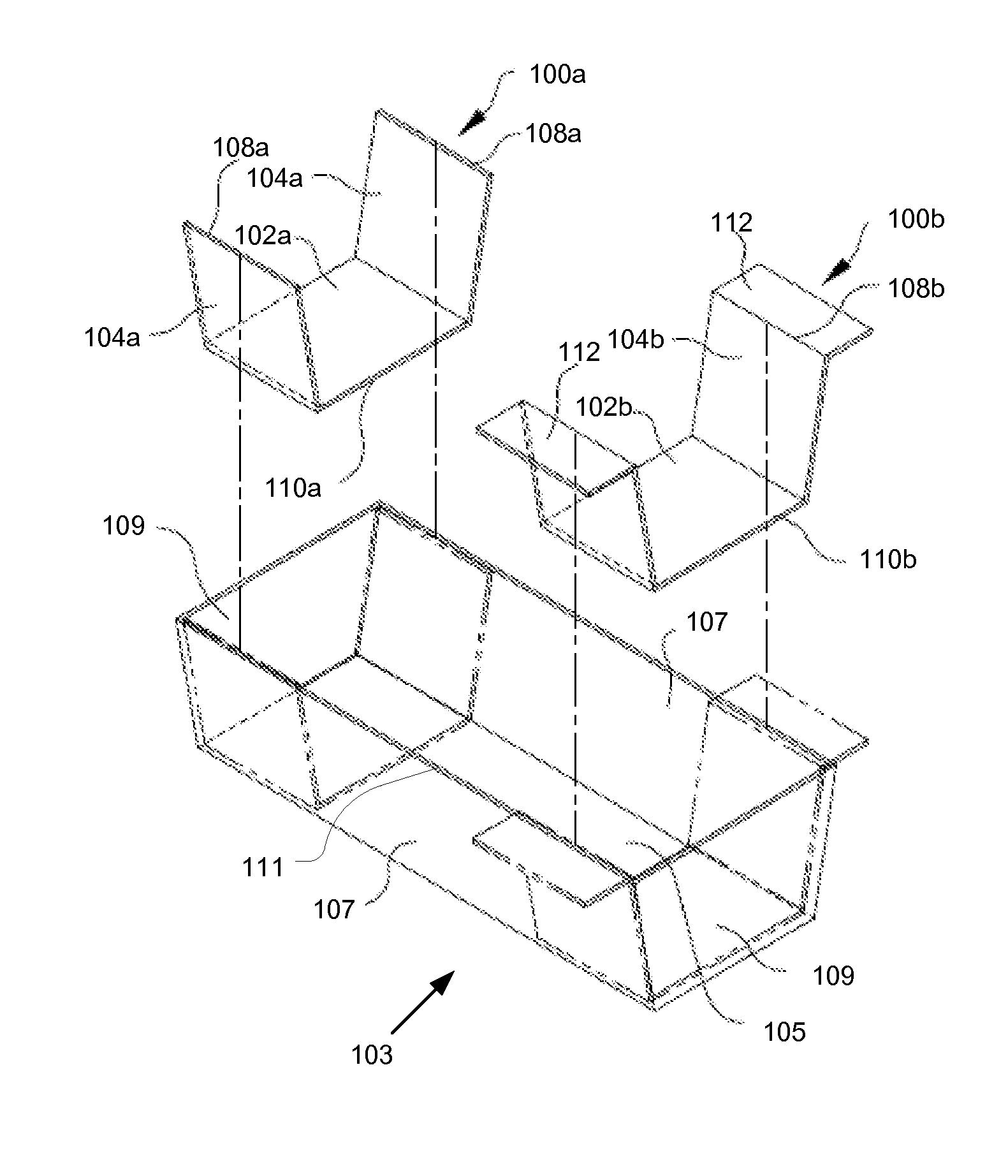
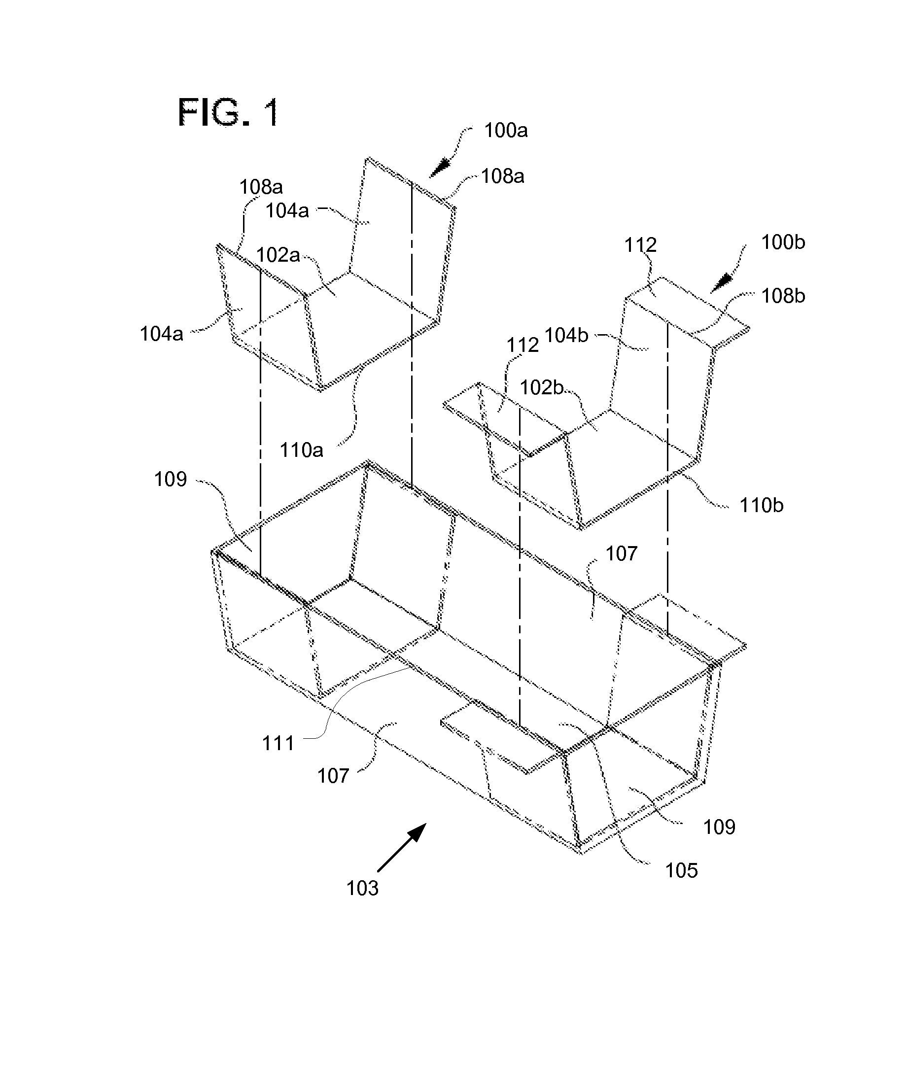
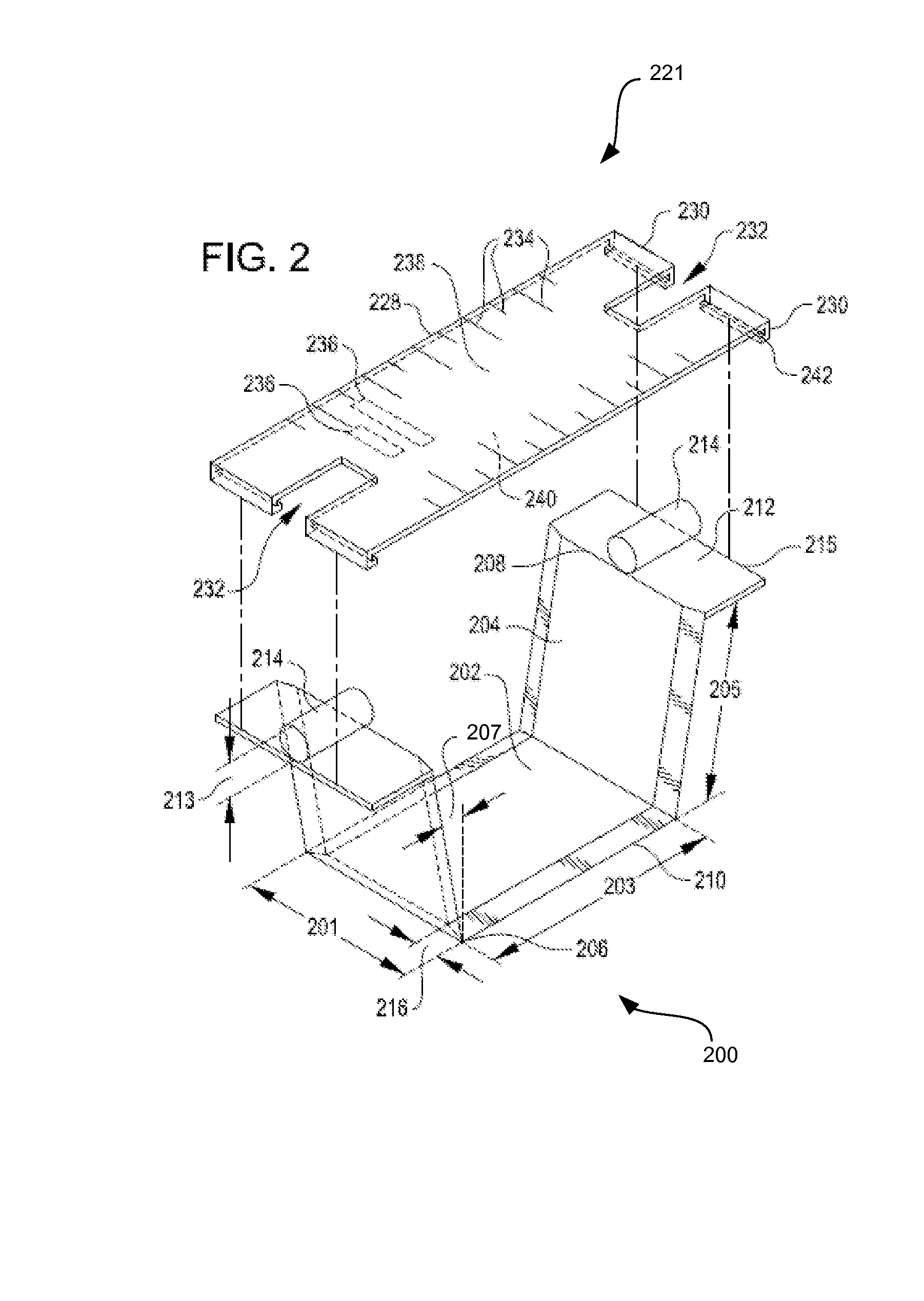
[0017]Embodiments herein are directed to a baking pan insert and to a system including the baking pan insert and a baking pan. The baking pan insert improves the process of removal of baked foods from a baking pan.

[0018]The term “baking pan” may be herein used not only to refer to baking pans according to their ordinary meaning, but may also refer to any container for cooking. The baking pan typically includes a bottom and at least two side walls.

[0019]In accordance with at least one embodiment, a...


PUM


Abstract

A baking pan insert having a bottom surface and two sides, configured to rest abutting the bottom and side interior surfaces of a baking pan, and configured to slide along a length of the baking pan, for aiding in the removal of portions of a baked good from the pan. In some embodiments, a baking pan has interior surface features, such as shelves, configured to guide the baking pan insert and optionally configured to receive a lid; and a baking pan insert may be configured to receive a guide to aid in cutting the baked good along a path corresponding to an edge of the bottom surface of the insert.

Description

CROSS-REFERENCES TO RELATED APPLICATIONS[0001]The present application claims the benefit and priority under 35 U.S.C. 119(e) of U.S. Provisional Application No. 61 / 930,885 filed Jan. 23, 2014 entitled, “BAKING PAN INSERT,” the entire contents of which is hereby incorporated by reference for all purposes.BACKGROUND OF THE INVENTION[0002]A baking pan is typically a flat-bottomed container made of metal, ceramic, glass, or other heat-tolerant material with sides and optional handles for aiding a user in removing the pan from an oven. Baking pans may be used to cook any of a wide variety of foods, including baked goods such as bread or pies and pasta dishes such as lasagna. Typically, foods cooked in a baking pan are removed from the pan by means of a spatula or other utensil and then plated.[0003]Baking poses several common frustrations including: adhesion, mess, and damage to the baking implements including the pan. The first of these frustrations, adhesion, relates to the possibility...

Claims


Application Information

Patent Timeline
Patent Type & Authority Applications(United States)
IPC IPC(8): A47J36/16B65D81/34B65D25/28A47J36/06A47J37/01
CPCA47J36/16A47J36/06B65D81/343B65D25/28A47J37/01A21B3/13A21B3/135A21B3/137
Inventor MOORE, SAMUEL KELLER
Owner PANOVATIONS
Why Eureka
Try Eureka