Lens cleaning apparatus

a technology of cleaning apparatus and lens, which is applied in the field of lens cleaning apparatus, can solve the problems of increasing the possibility of detection error or misdetection of other vehicles and lane markers, occupants have no access to find out the presence of white turbidity, and the observed image is distorted and/or blurred

Active Publication Date: 2015-07-23
CLARION CO LTD
View PDF6 Cites 31 Cited by
  • Summary
  • Abstract
  • Description
  • Claims
  • Application Information

AI Technical Summary

Benefits of technology

[0015]The lens cleaning apparatus according to claim 1 can sufficiently clean the lens by the cleaning mode selected in response to the turbidity degree, thereby enabling to clean the white turbidity on the lens surface sufficiently.

Problems solved by technology

Light incident on the lens is scattered by the white turbidity and generates a distortion and / or blur in the observed image, if the lens has the white turbidity.
The distortion and / or blur in the image cause decreases in contrasts of the detection target image (e.g., image of other vehicles or lane markers), thereby increasing occurrence possibility of a detection error of or a misdetection of the other vehicles and lane markers.
The detection error or misdetection may disturb an appropriate warning with respect to the positions of the other vehicles or lane markers.
Especially, in the system in which occupants in the vehicle are unable to check images taken by the camera, the occupants have no access to find out presence of the white turbidity on the lens.
Consequently, the detection error of or the misdetection may make the occupants distrust the system.

Method used


Image

  • Lens cleaning apparatus
  • Lens cleaning apparatus
  • Lens cleaning apparatus

Examples


embodiment 1

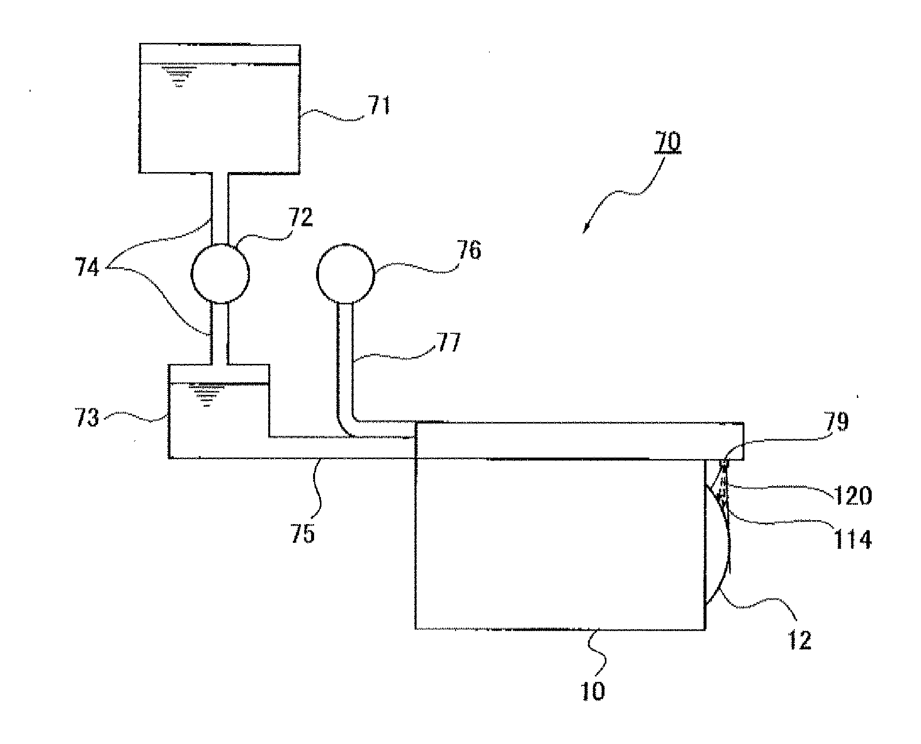
[0041]In this embodiment, the lens cleaning apparatus of the present invention is applied to a vehicle equipped with a blind spot warning (BSW) system, which monitors a rearward direction of the subject (host) vehicle and provides a warning if the BSW system detects an approaching vehicle traveling in adjacent lanes in the rearward direction of the subject vehicle.

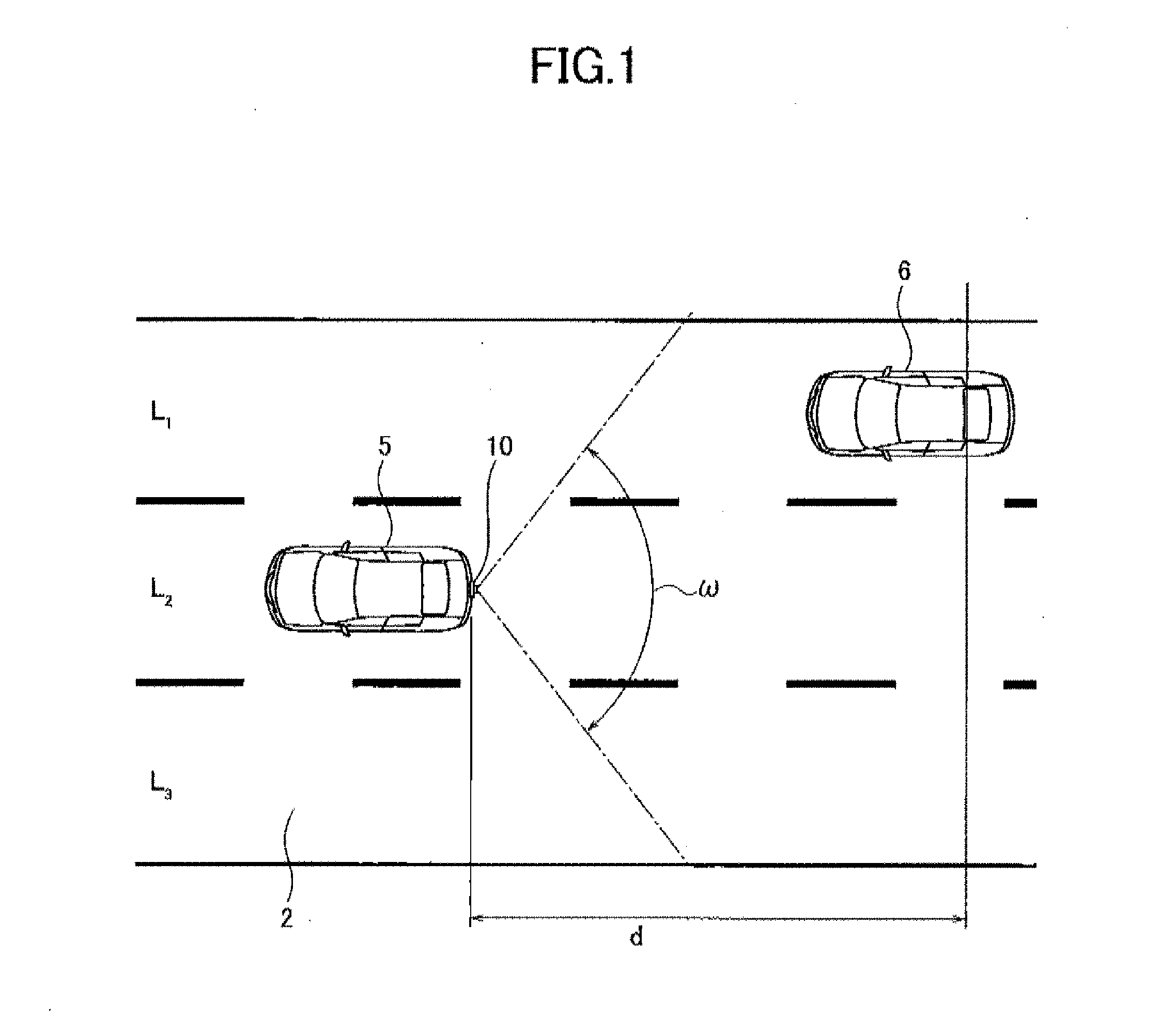
[0042]First, operation of the BSW system will be explained with reference to FIG. 1. An imaging unit 10 to monitor the rearward direction of the subject vehicle 5 is mounted backward in the rear of the subject vehicle 5 so as to take images of an area to, which includes the adjacent lanes on the right and left side in the rearward direction of the subject vehicle 5 (i.e., the area including lanes L1, L2, and L3 of the road 2). The system detects the approaching vehicle traveling in either lane L1 or L3 from the taken image by performing image processing on the image.

[0043]The BSW system is activated when the vehicle 5 is t...

embodiment 2

[0220]Next, a lens cleaning apparatus according to Embodiment 2 is explained.

[0221]As identical to Embodiment 1, the lens cleaning apparatus according to Embodiment 2 is applied to a vehicle having a BSW system. A difference between Embodiments 1 and 2 is that threshold values for selecting the cleaning mode with respect to the degree of the white turbidity U are changeable in response to use of a water-repellent lens, a degree of the water repellency, use of a hydrophilic lens, and a degree of the hydrophilicity.

[0222]The lens cleaning apparatus according to Embodiment 2 of the present invention is now explained.

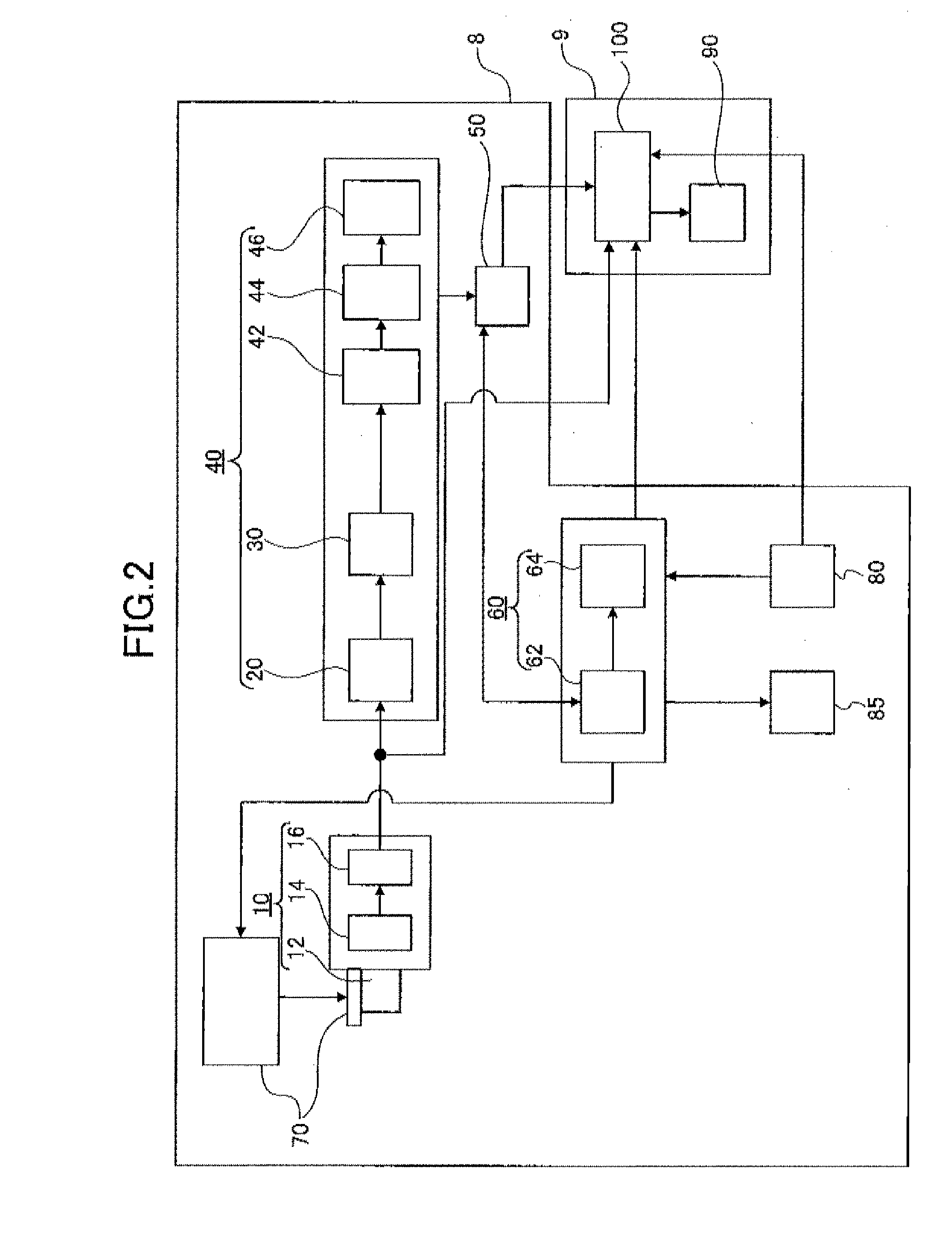
[0223]The configuration of the lens cleaning apparatus 8 according to Embodiment 2 is substantially the same as the configuration according to Embodiment 1. Hence, functional differences from Embodiment 1 are explained with reference to FIGS. 23A and 23B.

[0224]FIG. 23A shows a change of water repellency of the water repellent lens 12 in response to a change of a degree of t...


PUM


Abstract

A turbidity degree calculating unit calculates a degree of the white turbidity U on a surface of the lens based on a brightness gradient g of an image I (x, y), and a lens cleaning control unit sets a lens cleaning mode for spraying at least one of the cleaning fluid and the compressed air, which is performed by the lens cleaning unit, based on the calculated turbidity degree U.

Description

TECHNICAL FIELD[0001]The present invention relates to a lens cleaning apparatus for cleaning stain on a lens surface, which is generated from impurities that have been contained in water and deposited by drying the moisture.DESCRIPTION OF THE RELATED ART[0002]Recently, a vehicle circumference recognition system has been implemented. The system includes a camera mounted on a vehicle, observes the circumference of the subject vehicle using the camera, detects positions of other vehicles and / or traffic lane markers from the observed camera image, and determines a possibility of a contact with other vehicles and / or of lane departure based on the detected positions of other vehicles and / or traffic lane markers so as to warn the driver.[0003]In this type of the system, water splashed by the subject vehicle may attach to the lens surface of the camera when the vehicle runs in the rain, dust stirred up by the subject vehicle may attach onto the lens surface of the camera when the vehicle ru...

Claims


Application Information

Patent Timeline
Patent Type & Authority Applications(United States)
IPC IPC(8): B60S1/48B60S1/56H04N5/217B60S1/54
CPCB60S1/481H04N5/2171B60S1/56B60S1/54B60S1/0848B60S1/52G02B27/0006H04N23/811G06T7/174
Inventor IRIE, KOTAMURAMATSU, SHOJITAKEMURA, MASAYUKIHAYAKAWA, YASUHISAFUKATA, OSAMUUTAGAWA, AKIRA
Owner CLARION CO LTD
Why Eureka
Try Eureka