Battery pack with air-type cooling

a battery pack and air-type technology, applied in the field of batteries with air-type cooling, can solve the problems of increasing the self-discharge of batteries, reducing the capacity, and “thermal runaway” of batteries, and achieves significant heat removal, cost saving, and improved temperature control effect.

Active Publication Date: 2015-07-23
ROBERT BOSCH GMBH
View PDF4 Cites 3 Cited by
  • Summary
  • Abstract
  • Description
  • Claims
  • Application Information

AI Technical Summary

Benefits of technology

[0016]The solution proposed according to the invention is distinguished by the advantage that the temperature-control fluid, in the present case cooling air, for the temperature control of the at least one battery module or multiple battery modules can be extracted from the air-conditioned vehicle interior of a hybrid, electric or fuel cell vehicle, yielding the possibility of considerable cost savings. By means of the solution proposed according to the invention, it is ensured that, in the event of degassing, no battery cell becomes connected to the vehicle interior compartment. With the solution proposed according to the invention, a considerable increase in the effectiveness of temperature control can be attained, because the temperature-control fluid is conducted laterally past the battery cells and not just under the battery cells. This means that flow passes around the side surfaces of the individual battery cells, which are generally considerably larger, in particular more than four times larger, than the base surfaces of the battery cells. For this reason, in the concept proposed according to the invention, with a flow of cooling air laterally around battery cells, significant removal of heat is possible. In the case of the cooling air concept, it must be taken into consideration that the specific heat capacity Cwater is more than four times greater than the specific heat capacity Cair (at room temperature, Cwater is equal to 4.182 kJ / (kg·K), and Cair=1.005 kJ / (kg·K)).
[0017]By means of the solution proposed according to the invention, the individual battery cells are thermally coupled to one another by the ducts. In this way, reliable detection of the temperature of the battery cells is possible. Furthermore, by means of the solution proposed according to the invention, the need to attach temperature sensors to each one of the battery cells can be circumvented. Thermal coupling between the individual battery cells can be realized by means of the air ducts, which are preferably manufactured from a material with good heat-conducting properties, such as aluminum.
[0018]The ducts have a profile which preferably corresponds to a hyperbolic cosine (cos h) function. In this way, it is possible to realize very small wall thicknesses of the duct which is preferably manufactured as an extruded profile, said wall thicknesses being substantially in the region of 3 mm. Owing to the selected hyperbolic cosine function, it is possible to mechanically realize high strength with respect to lateral pressure, such that the profiles that have the ducts, when braced together, exhibit very high strength and can be braced against one another by means of tension straps. In the case of an average air gap width of approximately 3 mm, optimum flow conditions are retained with regard to the design of a fan which conveys the cooling air flow. The individual battery cells may also be accommodated in and held by a battery cell holder which serves, in effect, as a grid composed of air ducts. The ducts are sealed off with respect to the battery cell casings by means of a thermally stable dispenser seal. In the case of the design variant proposed according to the invention, in which the ducts run through side walls of a battery cell holder composed of aluminum, projecting lengths of the side surfaces protrude beyond the front and rear walls. It is ensured in this way that, at their passages through the front and rear walls, and also through the respective module front wall and module rear wall, reliable sealing at passage points can be realized with an electrically conductive sealing and adhesive compound. A self-contained temperature-control system is realized in this way.
[0019]By means of the solution proposed according to the invention, the space or the duct in which degassing of a battery cell can be realized is separated from the space or the duct from which the battery cells or the battery modules can be temperature-controlled, in particular cooled, by means of air of the vehicle originating from the passenger compartment. The sealing between said spaces or said ducts, for example at the battery cell holder, can be implemented in a reliable manner in process terms through formation of projecting lengths on the side walls formed on those walls of the battery cell holder which are to be joined together.

Problems solved by technology

Temperature changes and charging and discharging cycles lead to a decrease in capacity, and to an increase in the self-discharge of such batteries.
If more heat is generated in a battery cell than can be discharged to the surroundings, this can result in “thermal runaway”, with undesired consequences.

Method used


Image

  • Battery pack with air-type cooling
  • Battery pack with air-type cooling
  • Battery pack with air-type cooling

Examples


Embodiment Construction

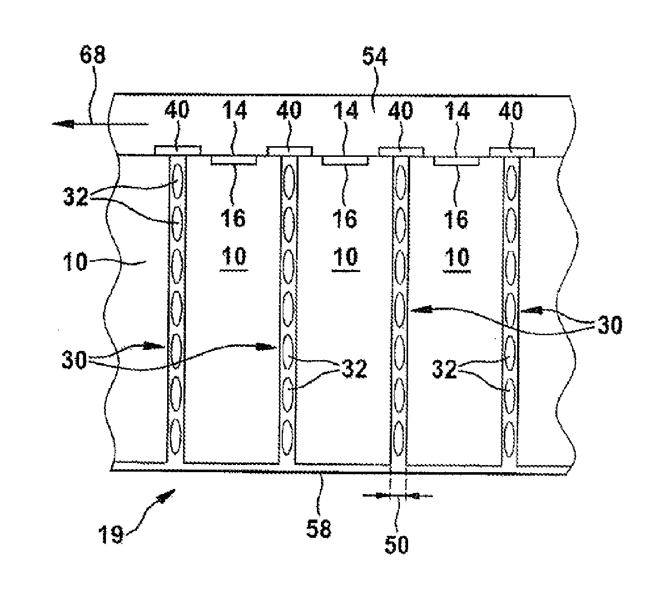
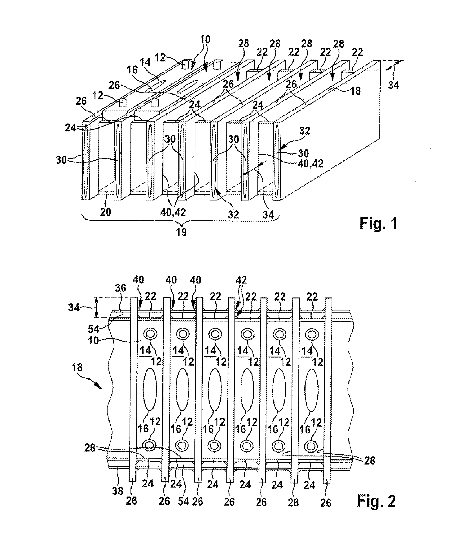
[0027]The illustration in FIG. 1 shows, in a perspective plan view, a battery cell holder which comprises individual battery cell compartments in which the battery cells of a battery module are accommodated.

[0028]FIG. 1 shows a battery module 19 which comprises a number of battery cells 10. The individual battery cells 10 each have cell terminals 12 which are arranged on a top side 14 of the battery cells 10. On the battery cell top side 14, there is situated a burst valve 16 which constitutes a predetermined breaking point of the battery cell housing, via which undesired degassing of the battery cell 10 can take place. The individual battery cells 10 are accommodated in an upright position in a battery cell holder 18 which is manufactured from aluminum or an aluminum alloy or from some other material which has good heat conduction characteristics.

[0029]The battery cell holder 18 has a base 20; individual battery cell compartments 28 for accommodating the battery cells 10 are separa...


PUM

PropertyMeasurementUnit
thicknessaaaaaaaaaa
operating temperatureaaaaaaaaaa

Abstract

A battery module (19) having a number of electrically interconnected battery cells (10), wherein the individual battery cells (10) are temperature-controlled by means of a temperature control fluid (70). Between the battery cells (10), there extends a duct system (30, 62, 66, 68) through which the temperature control fluid (70) flows. The duct system (30, 62, 66, 68) is separated completely from a degassing system (16, 54) of the battery cells (10).

Description

BACKGROUND OF THE INVENTION[0001]The invention relates to a battery module having a number of electrically interconnected battery cells, wherein the individual battery cells are temperature-controlled by means of a temperature control fluid.[0002]WO 2013 / 023847 A1 relates to a battery module with air-type cooling, and to a motor vehicle. The document discloses a battery module having a battery cell stack composed of at least two battery cells, wherein each battery cell is in contact with at least one air duct. The at least one air duct is integrated into the battery cell stack. In this way, despite a poor heat transfer coefficient, adequate cooling by means of an air stream of the battery cells is possible.[0003]US 2012 / 00150003 A1 relates to a battery module. Said battery module comprises a number of rechargeable battery cells, and a housing which accommodates the rechargeable battery cells. First heat dissipation fins project from the housing and have a polygonal shape or a closed...

Claims


Application Information

Patent Timeline
Patent Type & Authority Applications(United States)
IPC IPC(8): H01M10/6556H01M10/6557H01M2/12H01M50/209H01M50/224H01M50/227H01M50/233
CPCH01M10/5057H01M10/5059H01M2/12H01M10/653H01M10/647H01M10/6557H01M10/613Y02E60/10H01M50/30H01M50/209H01M50/233H01M50/224H01M50/227H01M10/60H01M10/65
Inventor SCHMIDT, ACHIMPANKIEWITZ, CHRISTIANLORENZ, LISABOEHME, JENSSTEIN, MATTHIASHORE, SARMIMALA
Owner ROBERT BOSCH GMBH
Why Eureka
Try Eureka