Device and method for detecting force factor of loudspeaker

a technology of force factor and loudspeaker, which is applied in the field of loudspeaker force factor detection devices and methods, can solve the problems of diaphragm excursion (i.e., the integral of velocity, v) cannot be obtained without, and the diaphragm property change, or a shorter lifetime, can not be achieved. , to achieve the effect of accurate detection of the force factor of the loudspeaker, increasing applicability and convenien

Inactive Publication Date: 2015-07-23
RICHTEK TECH
View PDF0 Cites 36 Cited by
  • Summary
  • Abstract
  • Description
  • Claims
  • Application Information

AI Technical Summary

Benefits of technology

[0022]The advantageous effect of the present invention over conventional approaches is that the present method is able to accurately detect the force factor of the loudspeaker under normal operati

Problems solved by technology

To protect the physical structure of a loudspeaker from being permanently damaged, it is a practice not to directly drive a loudspeaker with a linearly-amplified audio signal, which may, if the driving signal is too large, cause greater diaphragm excursion or even exceed beyond the displacement limit of the diaphragm excursion, thus leading to a change in the property, or a shorter lifetime, of the diaphragm of the loudspeaker, or even direct damage to the structure of the diaphragm.
Therefore, it has become an issue of the design of a loudspeaker and its driving

Method used


Image

  • Device and method for detecting force factor of loudspeaker
  • Device and method for detecting force factor of loudspeaker
  • Device and method for detecting force factor of loudspeaker

Examples


first embodiment

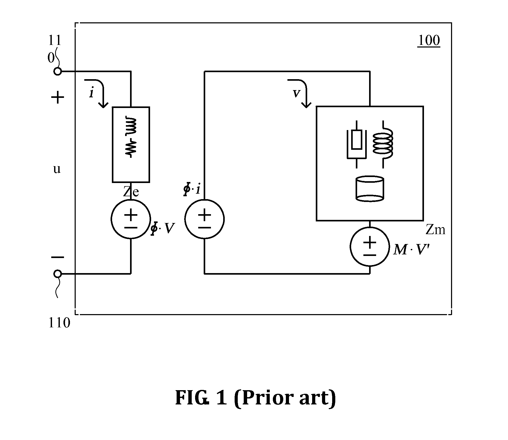
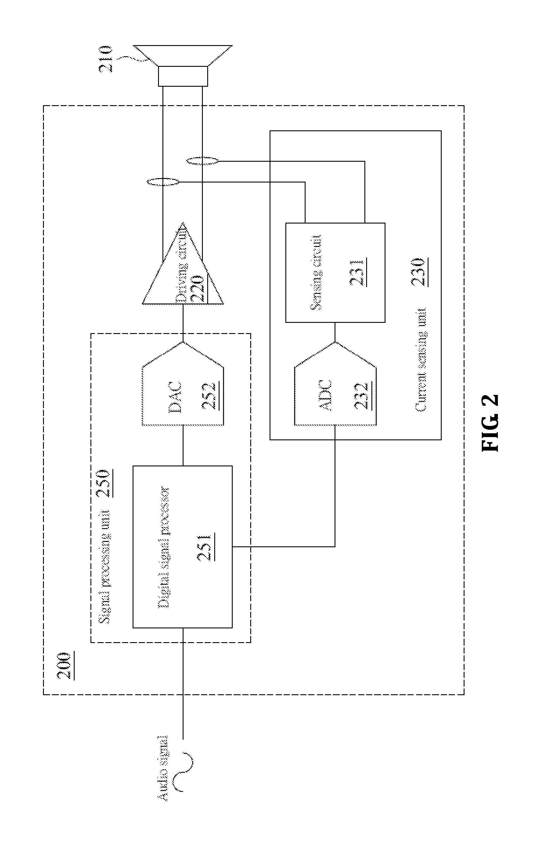
[0030]FIG. 2 shows a circuit diagram of a device 200 for detecting a force factor of a loudspeaker according to the present invention. The equivalent circuit of the loudspeaker 210 can be referred to FIG. 1 and its description. The device 200 for detecting the force factor includes a driving circuit 220, a current sensing unit 230, and a signal processing unit 250.

[0031]The driving circuit 220, coupled to the loudspeaker 210, receives a control signal generated from the signal processing unit and generates a dynamic driving voltage signal for driving the loudspeaker 210. For example, the dynamic driving voltage signal is a form of a sinusoid with a specified time period. The frequency of the sinusoid is either between the resonant frequency of the loudspeaker 210 and 1 Hz or vicinity of the resonant frequency of the loudspeaker 210. The frequency of the sinusoid can be set to a relatively lower frequency, for example, 100 Hz, if the detection operation is meant to be hidden from end...

second embodiment

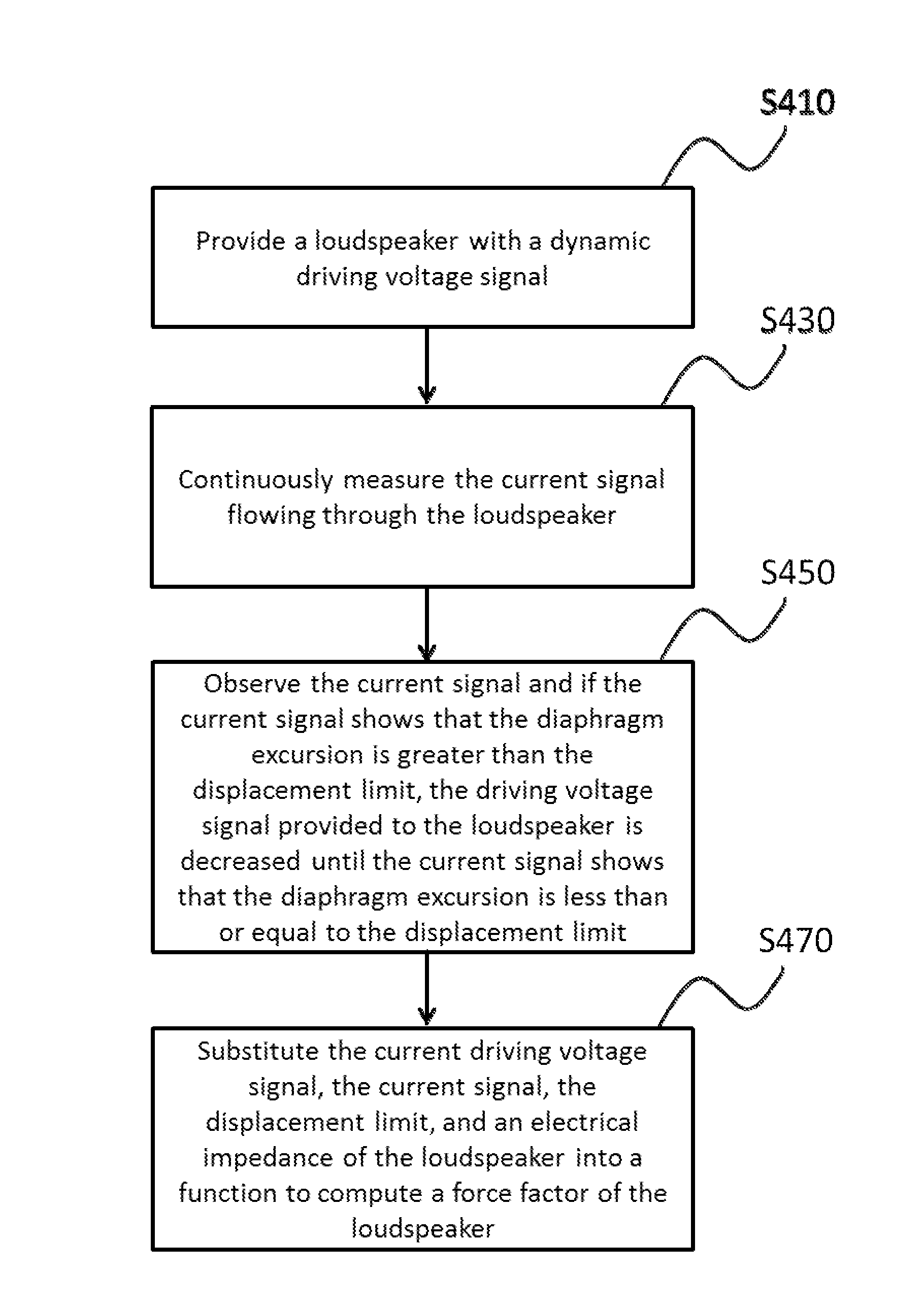
[0043]FIG. 4 is a flowchart of a method for detecting a force factor of a loudspeaker according to the present invention. The steps of the method are described as follows:

[0044]In step S410, provide a loudspeaker with a dynamic driving voltage signal. The dynamic driving voltage signal, for example, may be a form of a sinusoid with a specified time period, where the frequency of the sinusoid is either between the resonant frequency of the loudspeaker 210 and 1 Hz or vicinity of the resonance frequency of the loudspeaker 210. The frequency of the sinusoid can be set to a relatively lower frequency, for example, 100 Hz, if the detection operation is meant to be hidden from end users. A proper time period is determined based on the cycle of the said sinusoid. For example, when the frequency of the sinusoid is 100 Hz, the time period can be set to 10 ms, thus making the end users unaware of the sound wave for test purpose, where the sound wave is generated by the driving voltage signal....

third embodiment

[0048]FIG. 5 is a flowchart of a method for detecting a force factor of a loudspeaker according to the present invention. The steps of the method are described as follows:

[0049]The description of steps S510, S530, and S570 can be referred to the description of steps S410, S420, and S470 respectively, according to the second embodiment shown in FIG. 4.

[0050]In step S550, observe if the oscillating amplitude of the second derivative of the current signal is greater than a predetermined value and if the oscillating amplitude is greater than the predetermined value, which the diaphragm excursion of the loudspeaker is deemed to be greater than the displacement limit, decrease the driving voltage signal provided to the loudspeaker 210 until the oscillating amplitude of the second derivative of the current signal is less than or equal to the displacement limit, where the predetermined value is positively related to the magnitude of the driving voltage signal.

[0051]It should be noted that a...


PUM


Abstract

A method and device for detecting a force factor of a loudspeaker is provided. The method includes the steps of: providing the loudspeaker with a dynamic driving voltage signal; continuously measuring a current signal flowing through the loudspeaker; observing the current signal and if the current signal shows that the diaphragm excursion of the loudspeaker is greater than an displacement limit, decreasing the driving voltage signal until the current signal shows that the diaphragm excursion of the loudspeaker is less than or equal to the displacement limit; and substituting the current driving voltage signal, the current signal, the displacement limit, and an electrical impedance of the loudspeaker into a function so as to compute the force factor of the loudspeaker.

Description

CROSS REFERENCE TO RELATED APPLICATIONS[0001]This non-provisional application claims priority claim under 35 U.S.C. §119(a) on Taiwan Patent Application No. 103102385 filed Jan. 23, 2014, the entire contents of which are hereby incorporated by reference.BACKGROUND[0002]1. Field of the Invention[0003]The present invention relates to a device and method for detecting a force factor of a loudspeaker and, more particularly, to a device and method that are utilized by end users so as to accurately detect the force factor of a loudspeaker.[0004]2. Description of Related Art[0005]To protect the physical structure of a loudspeaker from being permanently damaged, it is a practice not to directly drive a loudspeaker with a linearly-amplified audio signal, which may, if the driving signal is too large, cause greater diaphragm excursion or even exceed beyond the displacement limit of the diaphragm excursion, thus leading to a change in the property, or a shorter lifetime, of the diaphragm of th...

Claims


Application Information

Patent Timeline
IPC IPC(8): H04R29/00H04R3/04
CPCH04R3/04H04R29/001
Inventor TSAI, KUO SHIH
Owner RICHTEK TECH
Why Eureka
Try Eureka