
Method and apparatus for setting uplink transmission power in wireless communication system

a wireless communication system and transmission power technology, applied in the field of wireless communication, can solve the problems of large power consumption, difficult control of the power of user equipment, and the maximum transmission power of user equipment, and achieve the effect of improving the efficiency of the scheduling of a bs and facilitating the execution of the uplink scheduling of the u

Active Publication Date: 2015-07-23
LG ELECTRONICS INC
View PDF2 Cites 84 Cited by
  • Summary
  • Abstract
  • Description
  • Claims
  • Application Information

AI Technical Summary

Benefits of technology

The patent text describes a method for efficient scheduling of uplink data transmission between a base station and a user equipment. This is achieved by taking into account the maximum transmission power of multiple serving cells. By doing so, the base station can optimize its uplink scheduling while ensuring that the user equipment operates within its maximum power limits. This helps to improve overall efficiency and performance of the network.

Problems solved by technology

In order to support the high transmission rate, that is, in order to increase a transmission capacity, to increase the bandwidth may be said to be essential, and to support a large bandwidth when a level of required service is low may cause great power consumption.
Furthermore, control of the power of user equipment encounters a more complicated situation because pieces of uplink transmission power of respective component carriers need to be comprehensively taken into consideration due to the introduction of multiple component carriers.
The complexity may cause problems in terms of maximum transmission power of user equipment.
If a base station performs scheduling that requires transmission power higher than the maximum transmission power, there may be a problem in that actual uplink transmission power exceeds maximum transmission power of user equipment.

Method used


Image

  • Method and apparatus for setting uplink transmission power in wireless communication system
  • Method and apparatus for setting uplink transmission power in wireless communication system
  • Method and apparatus for setting uplink transmission power in wireless communication system

Examples


Embodiment Construction

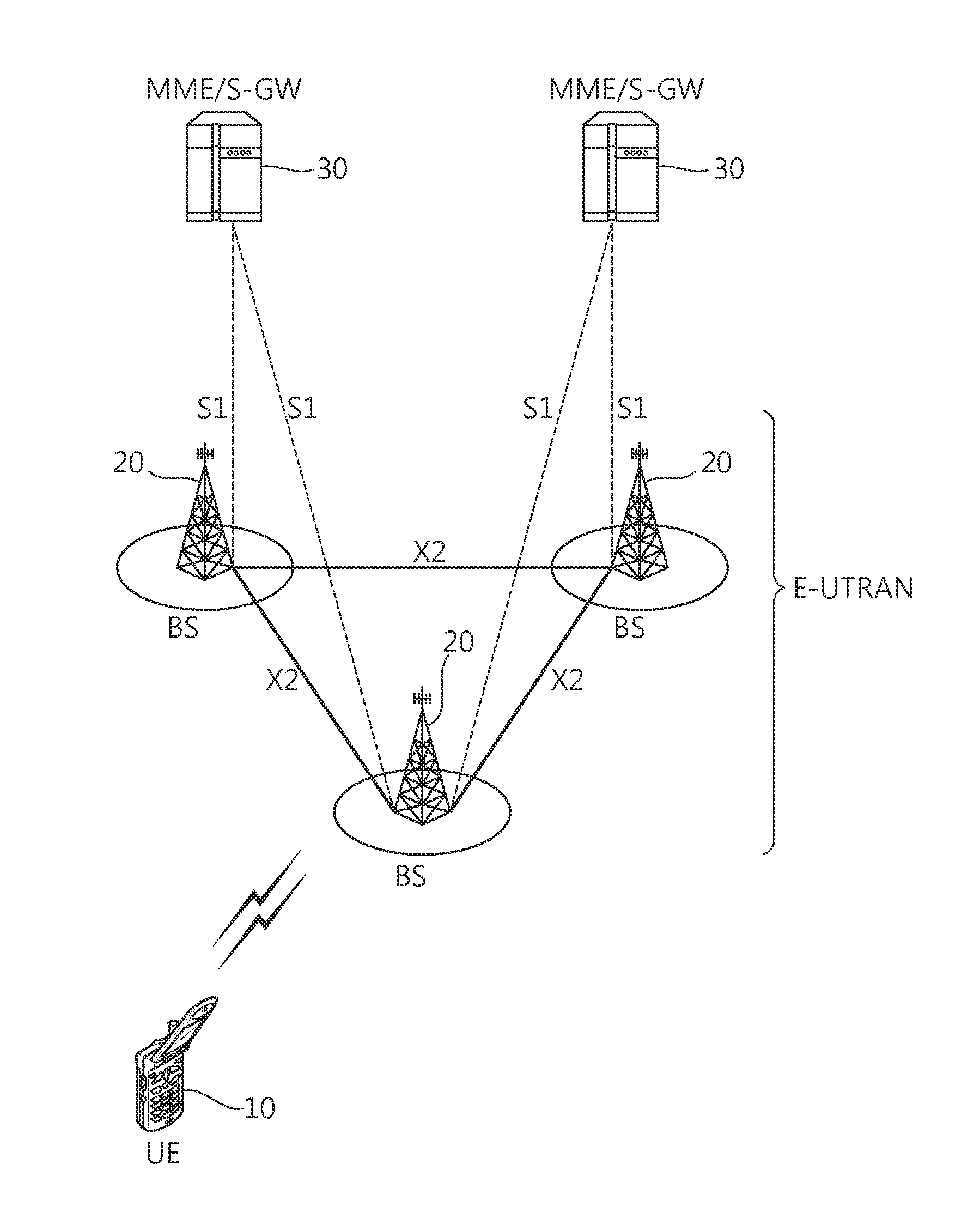
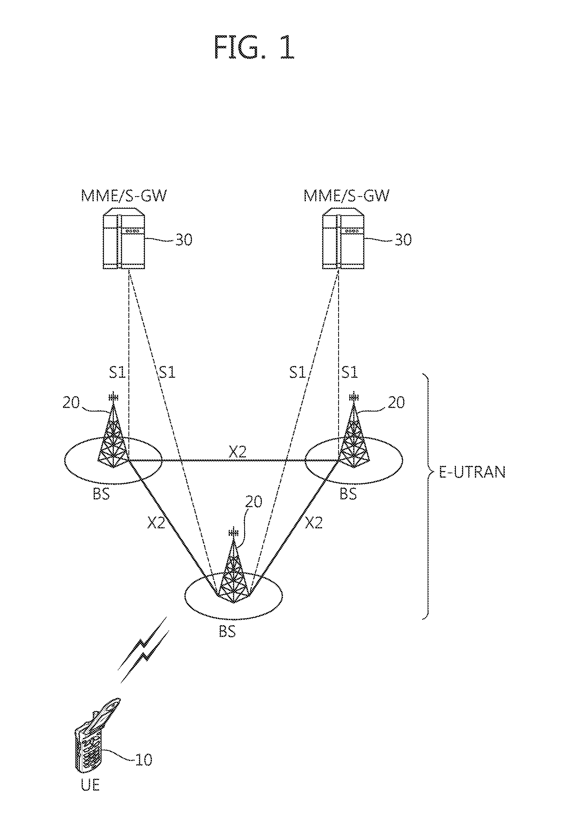
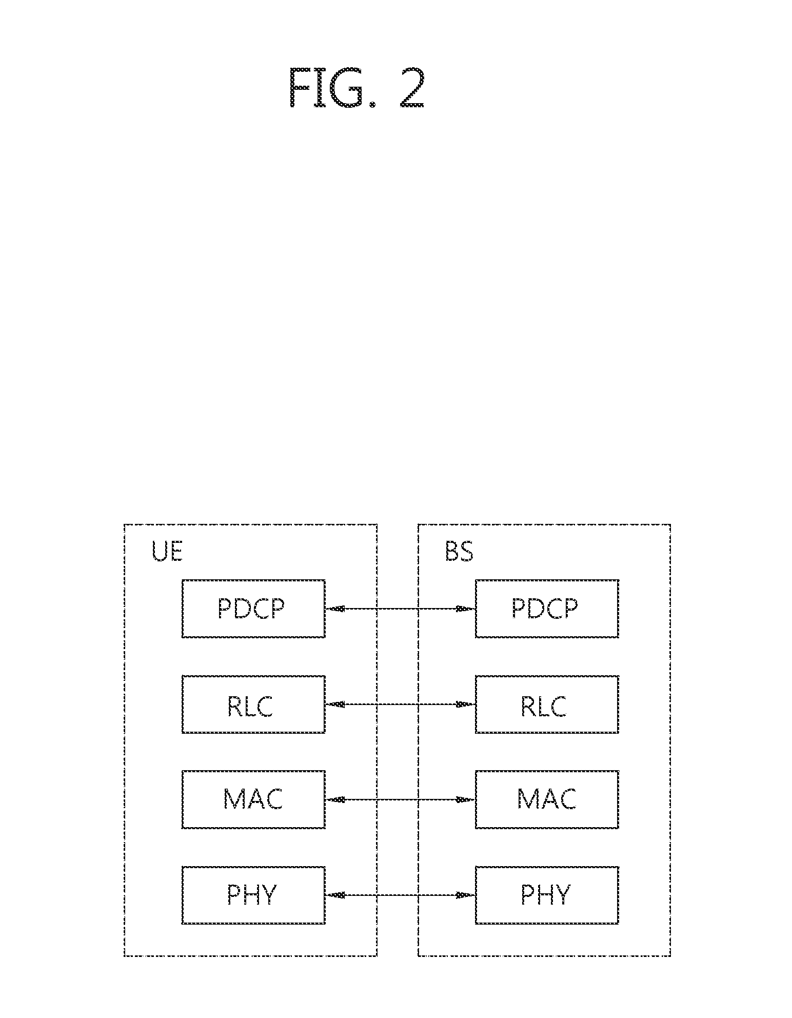
[0025]Hereinafter, in this specification, some embodiments are described in detail with reference to exemplary drawings. It is to be noted that in assigning reference numerals to elements in the drawings, the same reference numerals denote the same elements throughout the drawings even in cases where the elements are shown in different drawings. Furthermore, in describing the embodiments of the present invention, a detailed description of the known functions and constitutions will be omitted if it is deemed to make the gist of the present invention unnecessarily vague.

[0026]In this specification, a communication network is described as a target, and tasks performed in a communication network may be performed in a process of controlling, by a system (e.g., a base station) controlling the communication network, and sending data or may be performed in user equipment linked to the corresponding network.

[0027]FIG. 1 shows a wireless communication system to which the present invention is ...


PUM


Abstract

Provided are a method and a terminal device for setting uplink transmission power in a wireless communication system. A terminal acquires information on the time alignment group (TAG) for multiple supportable serving cells so as to constitute TAGs, checks whether an overlap section of subframe n and subframe n+1 for uplink transmission exists between TAGs, and sets uplink transmission power so as to scale the uplink transmission power (PCMAX) within the range that does not exceed the configured maximum transmission power (PCMAX) of the terminal in the checked overlap section. Here, the uplink transmission power considers the maximum transmission power for multiple serving cells contained in the TAGs.

Description

BACKGROUND OF THE INVENTION[0001]1. Field of the Invention[0002]The present invention relates to wireless communication and, more particularly, to a method and apparatus for setting uplink transmission power in a wireless communication system, which support a plurality of component carriers.[0003]2. Related Art[0004]In recent years, the commercialization of long term evolution (LTE) systems, that is, next-generation wireless communication systems, is being supported in earnest. The LTE system is spread more rapidly as a need to guarantee the activity of UE users and to support high-capacity service of high quality for user demands as well as voice services is recognized. The LTE system provides the improvements of low transmission delay, a high transmission rate, a system capacity, and coverage.[0005]To this end, the LTE system supports a carrier aggregation (hereinafter referred to as a ‘CA’). The CA means the support of a plurality of carriers and is also called a spectrum aggrega...

Claims


Application Information

Patent Timeline
IPC IPC(8): H04W52/14H04W52/34
CPCH04W52/34H04W52/146H04W52/367
Inventor AHN, JOONKUIYANG, SUCKCHELYI, YUNJUNGSEO, DONGYOUN
Owner LG ELECTRONICS INC
Learn More