Optimal design of a lower limb exoskeleton or orthosis

a technology of exoskeleton and lower limb, applied in the field of optimal design of lower limb exoskeleton or orthosis, can solve the problems of reducing flexibility, inconvenience for users, and disrupting device function, so as to augment or rehabilitate the physical capabilities of individuals, avoid mismatch between limb joint motion and mechanical interface motion, and improve comfort and lightness

Active Publication Date: 2015-07-30
MASSACHUSETTS INST OF TECH
View PDF2 Cites 84 Cited by
  • Summary
  • Abstract
  • Description
  • Claims
  • Application Information

AI Technical Summary

Benefits of technology

[0023]The device of the present invention employs a geometric configuration that does not require artificial joints, therefore, making the device more comfortable and lighter. The comfort and weight of the device of the invention plays a large role in its ability to augment or rehabilitate the physical capabilities of an individual wearing the device.
[0024]The device of the invention can constrain the linkage system and set trajectories of instantaneous centers of the device in accordance with normal biological joint motions while the external sources apply torques to the joint at the same time. As a result, mismatch between limb joint motion and mechanical interface motion is largely avoided, as well as skin shear force, undesired slippage and sluggish interaction between the individual and the device.
[0025]The device of the invention can also act in the sagittal plane so that external sources can apply torques to joints of the individual without impeding rotation of the joint in the other planes, i.e., coronal or transverse. As a result, mismatch between biological ankle joint motion and mechanical interface motion is greatly avoided, as well as undesired large additional inertia added by the device worn by the individual.
[0026]In still another aspect of this invention, a force balance transmission is maintained in the sagittal plane of the individual so that external...

Problems solved by technology

Typically, the exoskeleton uses a mechanical joint in parallel with the anatomical joint, which reduces flexibility, or the force distributions are parallel to the axis of the limb (i.e. shear), which may be uncomfortable to the user.
This discomfort often disrupts device function and hinders the efficacy of the exoskeleton.
Known powered exoskeletons are also typically heavy and cumbersome to use....

Method used


Image

  • Optimal design of a lower limb exoskeleton or orthosis
  • Optimal design of a lower limb exoskeleton or orthosis
  • Optimal design of a lower limb exoskeleton or orthosis

Examples


Embodiment Construction

[0066]A description of example embodiments of the invention follows.

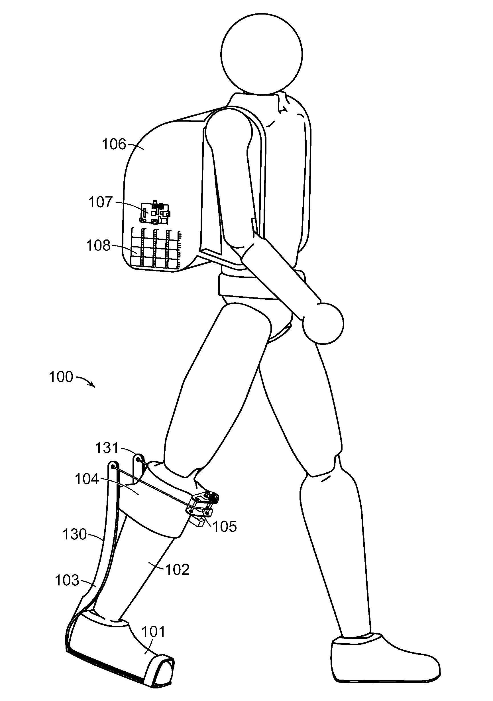
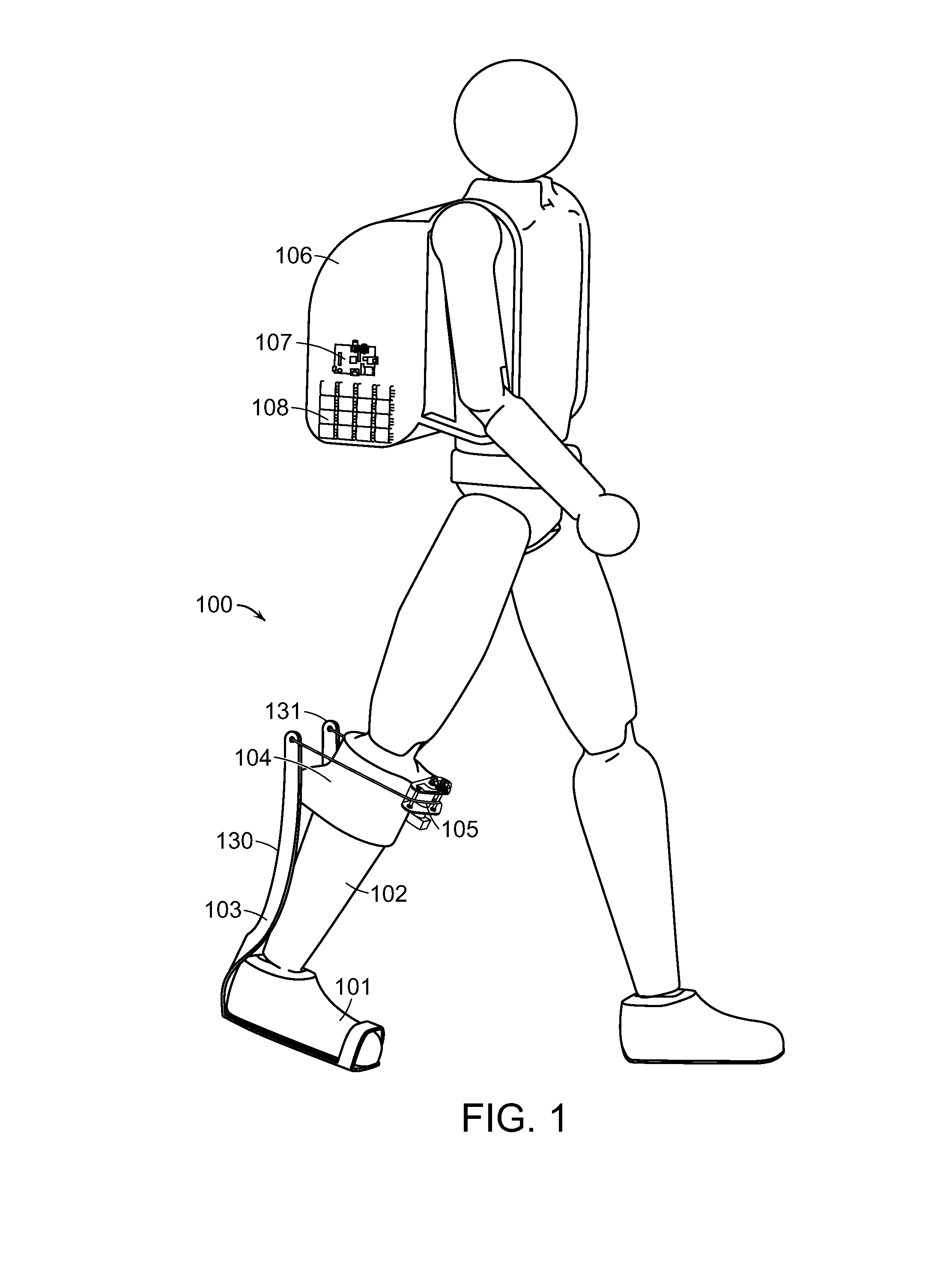
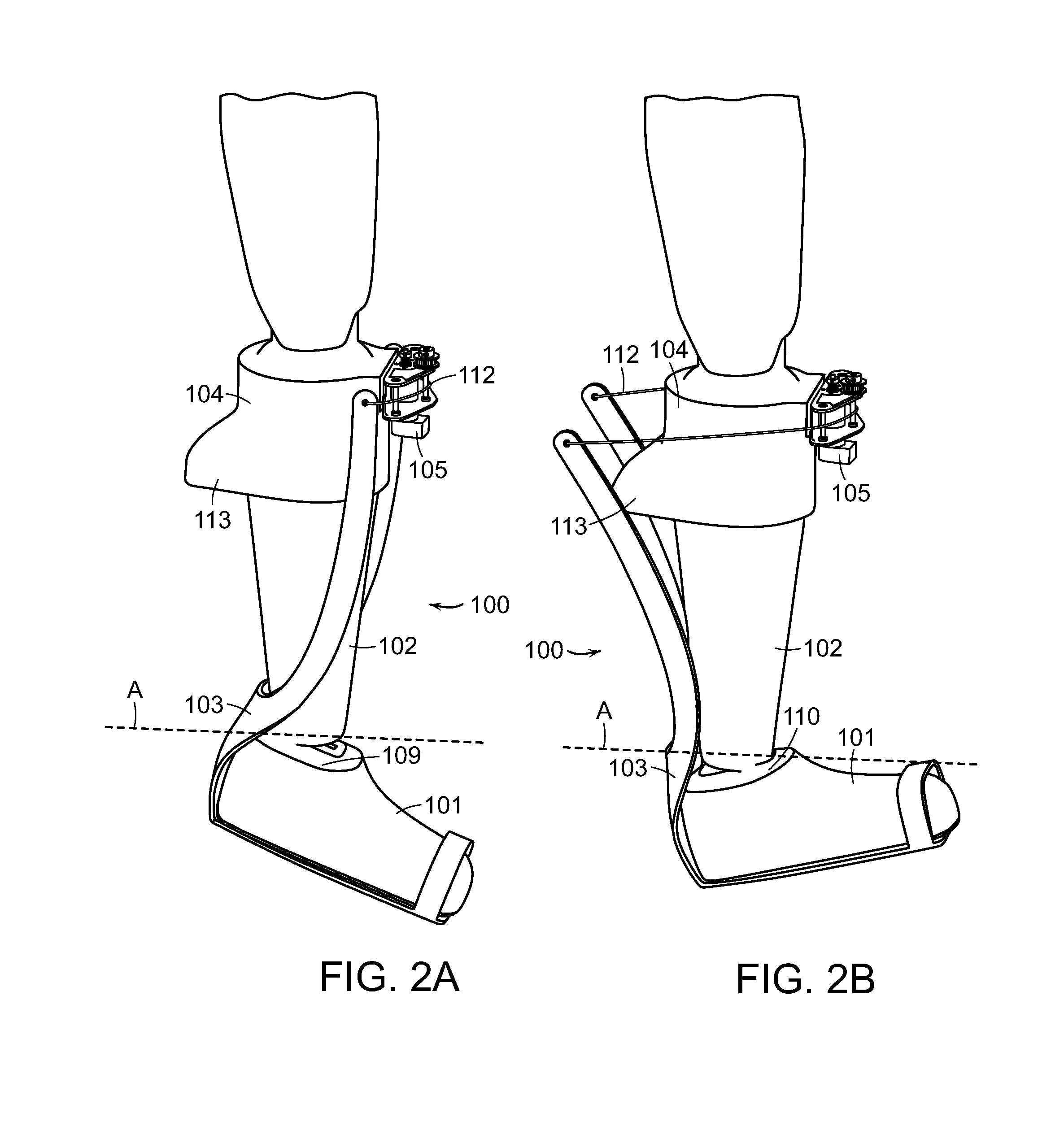
[0067]The invention is directed to an assistive or augmenting device that physically interacts with a person. One part of the invention is directed to a lower limb joint exoskeleton that physically interfaces with a person. A second part of the invention is directed to a joint exoskeleton or assistive device that physically interfaces with a person without having a significant mismatch between limb joint motion and mechanical interface motion in the same plane. A third part of the invention is directed to an ankle joint exoskeleton or assistive device that interfaces with a person without adding significant additional leg inertia to the human body or impeding ankle joint motion. A fourth part of the invention is directed to a device that enables external-internal rotation and inversion-eversion rotation while applying a torque in the sagittal plane, so that an attached biological ankle joint can maintain the normal ...


PUM


Abstract

A link extends between a distal member and a proximal member of a wearable device, such as an exoskeleton, orthosis or prosthesis for a human lower limb. One or other of the distal member and the proximal member includes a crossing member. The link extends from the crossing member of the distal member or the proximal member, to the other of the distal member or the proximal member. Actuation of the link translates to a force at the distal or proximal member that is normal to a major longitudinal axis extending through the distal and proximal members. In one embodiment, a sliding link of a device configured for use with a human joint tracks two degrees of freedom of the joint.

Description

RELATED APPLICATIONS[0001]This application claims the benefit of U.S. Provisional Application No. 61 / 916,692, filed on Dec. 16, 2013 and U.S. Provisional Application No. 62 / 014,377, filed on Jun. 19, 2014. The entire teachings of the above applications are incorporated herein by reference.GOVERNMENT SUPPORT[0002]This invention was made with Government support under Grant No. NNX12AM16G awarded by the National Aeronautics and Space Agency. The Government has certain rights in the invention.BACKGROUND OF THE INVENTION[0003]Exoskeletons, orthoses and prostheses are intended to enhance human function, often in the context of locomotory motion. Exoskeletons, for example, are worn on the body exterior, around a biological joint that is the target of an intended function (e.g., knee or hip). Depending on the exact purpose of the device, the mechanical effect of the exoskeleton may be to add, remove or store and release energy. Irrespective of purpose, however, all exchange of energy betwee...

Claims


Application Information

Patent Timeline
IPC IPC(8): A61H3/00A61F2/64A61F2/66A61F2/60
CPCA61H3/00A61F2/6607A61F2/64A61F2/605A61F2/60A61F5/0102A61H1/0237B25J9/0006A61F2005/0132A61F2005/0155A61F2005/0179A61H2201/1207A61H2201/1238A61H2201/1261A61H2201/14A61H2201/164A61H2201/165A61H2201/1657A61H1/024A61H1/0244A61H1/0266A61H2201/1215A61H2201/1409A61H2201/1436A61H2201/1628A61H2201/1676A61H2201/5007A61H2201/5061A61H2201/5069A61H2201/5071A61H2201/5082A61H2201/5084A61H2230/605A61H2201/149
Inventor HERR, HUGH M.MOONEY, LUKE M.ROUSE, ELLIOTT J.KUAN, JIUN-YIH
Owner MASSACHUSETTS INST OF TECH
Why Eureka
Try Eureka