Removing bubbles in microfluidic systems

a microfluidic system and bubble technology, applied in the field of microfluidic systems, can solve the problems of affecting the operation of the system, harming the biologic elements, and impede the flow of fluid through the system

Active Publication Date: 2015-07-30
PRESIDENT & FELLOWS OF HARVARD COLLEGE
View PDF15 Cites 50 Cited by
  • Summary
  • Abstract
  • Description
  • Claims
  • Application Information

AI Technical Summary

Benefits of technology

[0008]The present invention is directed to fluidic and microfluidic devices and systems that can be used to grow and sustain biologic elements such as cells, tissues and organs. In operation, these fluidic and microfluidic devices and systems utilize the flowing fluids to distribute media, nutrients, and other materials useful for culturing and sustaining the biologic cells, tissues and organs. The introduction of air or gas bubbles into these systems can impede the flow of fluid through the system and potentially harm the cells, tissues and organs. In addition, bubbles inadvertently introduced into the system can significantly and negatively affect device operation and experimental outcomes. In accordance with some embodiments of the invention, a bubble trap can be integrated into or directly connected to fluidic and microfluidic devices to avoid the problems caused by bubbles inadvertently introduced in to the system.

Problems solved by technology

In the prior art, fluidic and microfluidic devices are typically interconnected into systems that include many individual fluidic and microfluidic components connected by a complicated and cumbersome arrangement of tubing, valves and pumps.
In some configurations, these gas bubbles, such as air bubbles, can negatively impact the operation of the system and can harm the biologic elements that can reside in the various components of the system.
The introduction of air or gas bubbles into these systems can impede the flow of fluid through the system and potentially harm the cells, tissues and organs.
In addition, bubbles inadvertently introduced into the system can significantly and negatively affect device operation and experimental outcomes.

Method used


Image

  • Removing bubbles in microfluidic systems
  • Removing bubbles in microfluidic systems
  • Removing bubbles in microfluidic systems

Examples


Embodiment Construction

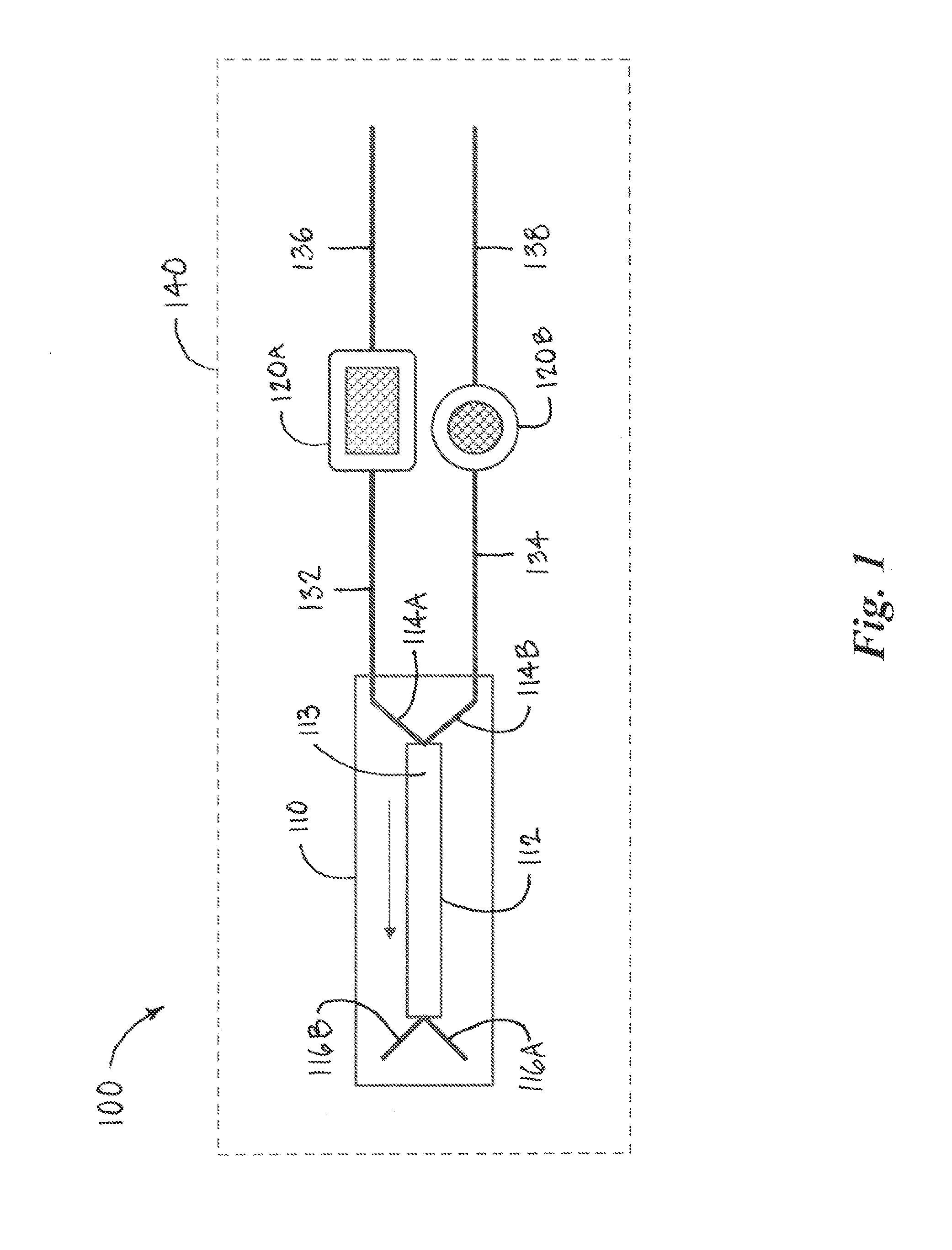
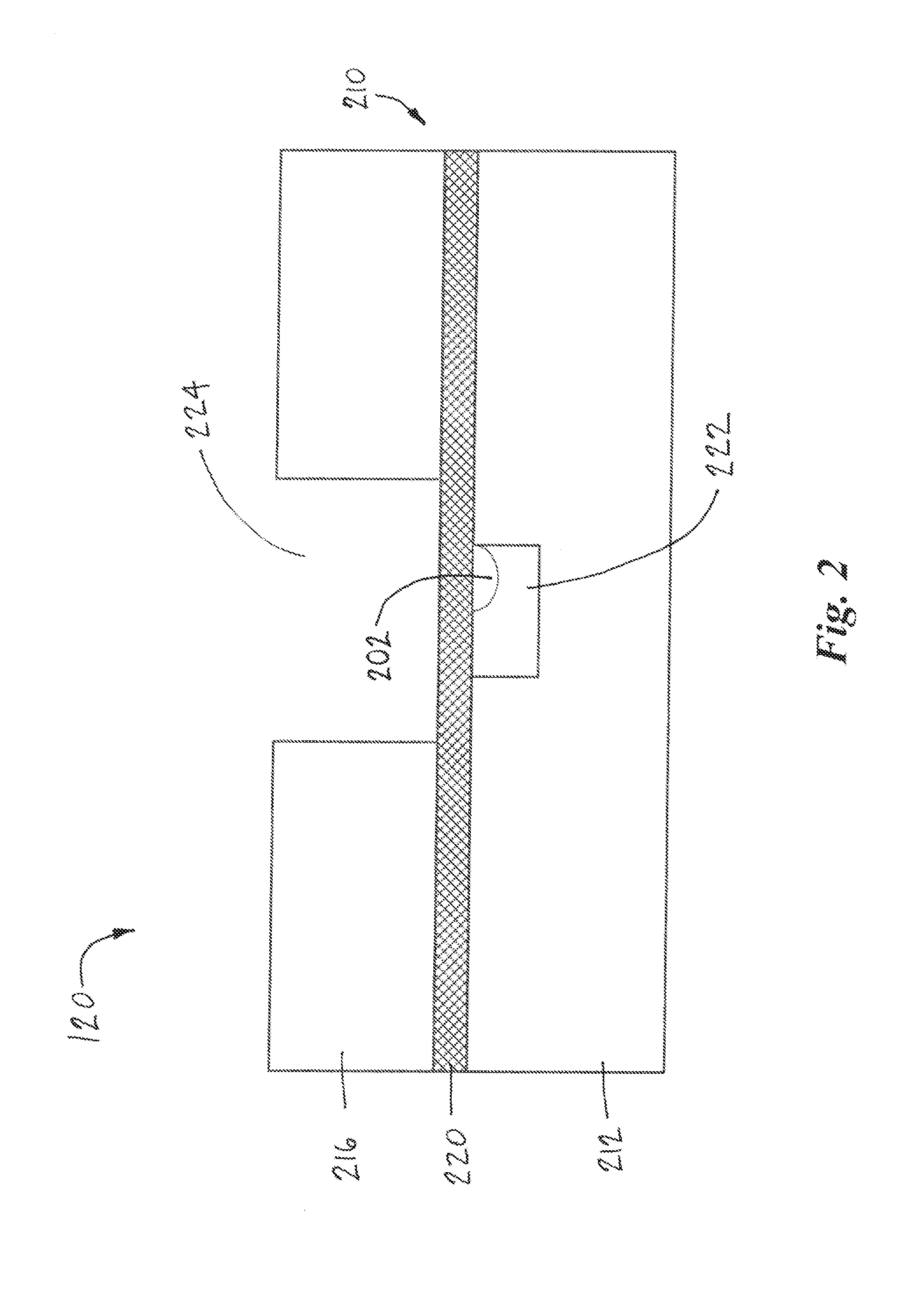
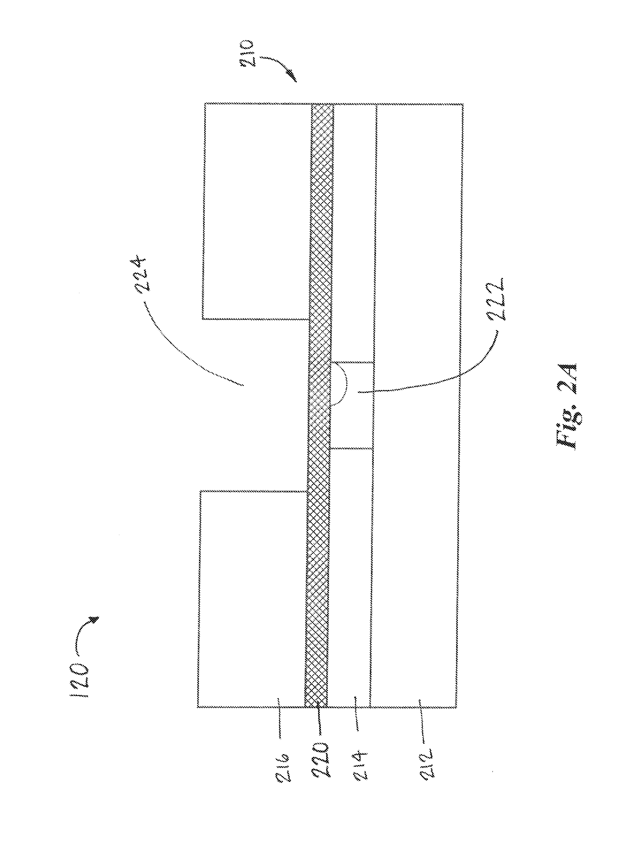
[0027]For purposes of illustration, aspects of the present invention will be described in the context of diagrammatic examples of microfluidic systems according to embodiments of the invention. As used herein the terms fluidic and microfluidic, unless the context clearly indicated otherwise, are used interchangeably. While the inventions may, in some circumstances, be better suited for use with microfluidic devices and systems, the inventions may, in some circumstances, also be better suited for use with fluidic devices and system.

[0028]The invention is directed to a microfluidic system that includes one or more microfluidic devices connected to other devices or components that make up a microfluidic system or a part thereof. As used herein the term microfluidic device is intended to refer to devices that include one or more microfluidic channels that are adapted to carry fluids between components. In accordance with some embodiments of the invention, the cross-sectional distance of...


PUM

PropertyMeasurementUnit
cross-sectional distanceaaaaaaaaaa
thicknessaaaaaaaaaa

Abstract

A microfluidic system includes a microfluidic device connected to a bubble trap device whereby fluid flowing to the microfluidic device passes through the bubble trap device to remove gas bubbles prior to entering the microfluidic device. The bubble trap can include a separation chamber and an exhaust chamber separated by a hydrophobic porous membrane and gas bubbles in the fluid entering the separation chamber pass through the hydrophobic porous membrane into the exhaust chamber while the fluid remains in the separation chamber. The bubble trap can be formed by bonding a first body portion to a first side of the hydrophobic porous membrane and bonding a second body portion to a second side of the hydrophobic porous membrane. The exhaust chamber can be connected to an elongated exhaust channel that limits the evaporation losses of the fluid through the hydrophobic porous membrane.

Description

CROSS-REFERENCE TO RELATED APPLICATIONS[0001]This application claims benefit under 35 U.S.C. §119(e) of U.S. Provisional Application No. 61 / 696,997 filed on Sep. 5, 2012 and U.S. Provisional Application No. 61 / 735,215 filed on Dec. 10, 2012, the contents of each of which are incorporated herein by reference in their entireties.GOVERNMENT SUPPORT[0002]This invention was made with government support under grant no. W911NF-12-2-0036 awarded by DARPA / U.S. Department of Defense. The government has certain rights in the invention.REFERENCE TO MICROFICHE APPENDIX[0003]Not ApplicableBACKGROUND[0004]1. Technical Field of the Invention[0005]The present invention is directed to microfluidic systems and devices for use in microfluidic systems that can be used to remove bubbles. More specifically, the present invention is directed to bubble separating or trapping devices that can be used to remove bubbles from fluids flowing into microfluidic devices, such as, organ-on-a-chip or organ chip devic...

Claims


Application Information

Patent Timeline
Patent Type & Authority Applications(United States)
IPC IPC(8): B01L3/00B01D19/00C12M1/107C12M3/06C12M1/04
CPCB01L3/502723C12M23/16C12M23/24C12M23/36B01L3/502715B01L2200/0684B01L2300/087B01L2300/0877B01L2300/06B01L2300/0864B01D19/0031B01D17/085B01D63/088B01D71/36B01D2325/38B01L2300/0816B01L2300/0874B01L2300/0887
Inventor INGBER, DONALD E.HAMILTON, GERALDINE A.LEVNER, DANIELHINOJOSA, CHRISTOPHERPATTERSON, DANIEL
Owner PRESIDENT & FELLOWS OF HARVARD COLLEGE
Why Eureka
Try Eureka