Sub-frame Radial Bogie

a radial bogie and subframe technology, applied in the direction of rail engagement elements, axle box mounting, transportation and packaging, etc., can solve the problems of affecting the stability of operation and derailment, and the impact of the critical speed of hunting, so as to reduce the dead weight of the assembled wheelset radial device, reduce the unsprung weight of the bogie, and reduce the dynamic interaction between the wheel and the rail

Active Publication Date: 2015-07-30
CRRC MEISHAN
View PDF1 Cites 7 Cited by
  • Summary
  • Abstract
  • Description
  • Claims
  • Application Information

AI Technical Summary

Benefits of technology

[0018]1 The sub-frame and the adapters are of split casting structure, thus greatly reducing dead weight of the assembled wheelset radial device, reducing unsprung weight of the bogie, effectively reducing wheel-rail dynamic interaction, and improving dynamics performance of the rolling stock.
[0019]2 The sub-frame is connected with the adapters by pulling rivets so that the sub-frame bears longitudinal and transverse loads only, which improves stress condition of the sub-frame and prolongs fatigue life thereof effectively.
[0020]3 The sub-frame is connected with the adapter

Problems solved by technology

For the railway freight car bogie, shear rigidity of the bogie is an important parameter affecting straight line operation stability thereof and can directly impact critical speed of hunting instability, operation stability and derailment safety of a rolling stock.
Meanwhile, flexural rigidity is also an important parameter affecting curving performance of the bogie and can directly impact wheel wear rate and wheel-track force.
Despite the advantages of simple structure and convenient manufacturer and maintenance, the two types of bogies can not match the shear rigidity and flexural rigidity reasonably.
Thus, critical speed and curving performance of rolling stocks can not be met at the same time, failing to meet the needs of high-speed economic development.
Firstly, in order to ensure that the sub-frame has enough strength and

Method used


Image

  • Sub-frame Radial Bogie
  • Sub-frame Radial Bogie
  • Sub-frame Radial Bogie

Examples


Embodiment Construction

[0034]In order to make the object, technical solution and advantages of the invention more clear, the technical solution of the invention will be described clearly and completely in combination with accompanying drawings and examples. Obviously, the examples described herein are only part of examples of the invention rather than all examples. Based on the examples of the invention, all other examples obtained by those of ordinary skill in the art without creative work fall within the protection scope of the invention.

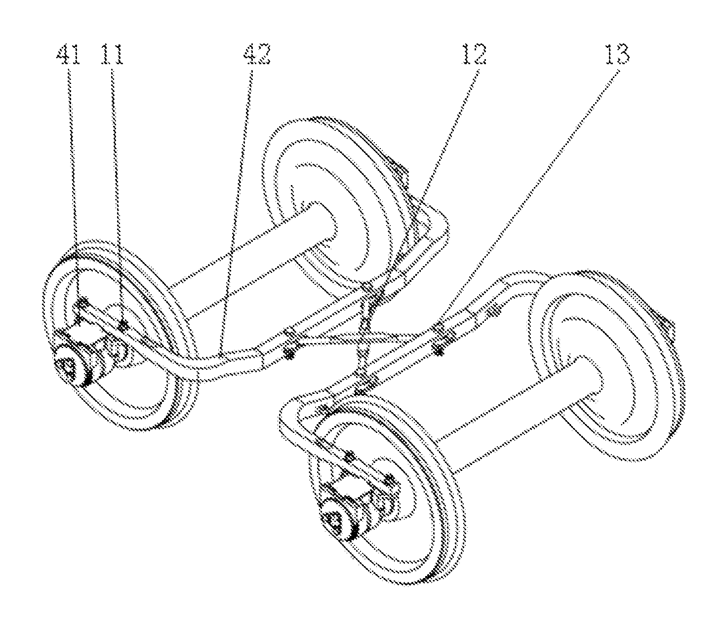
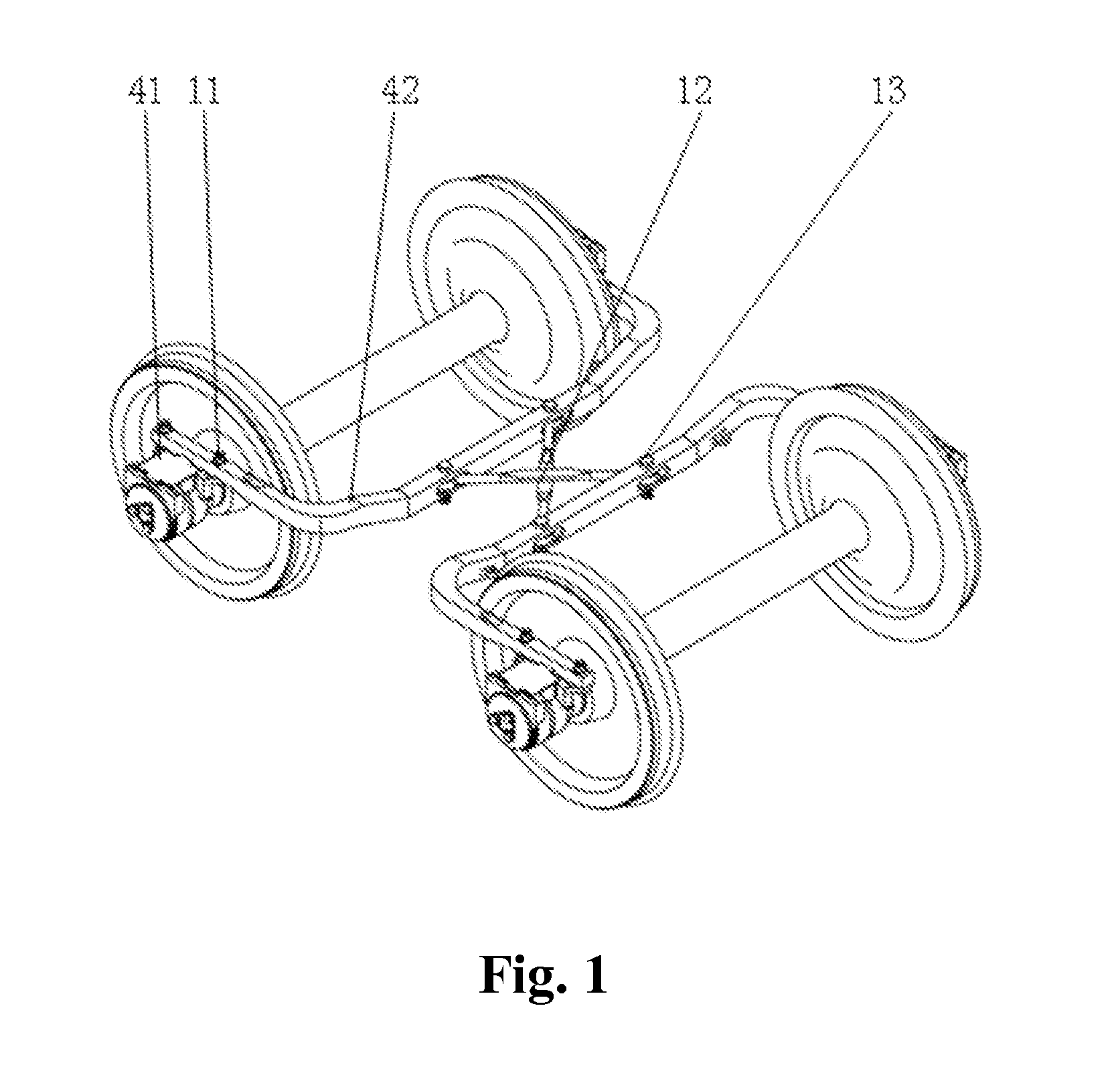
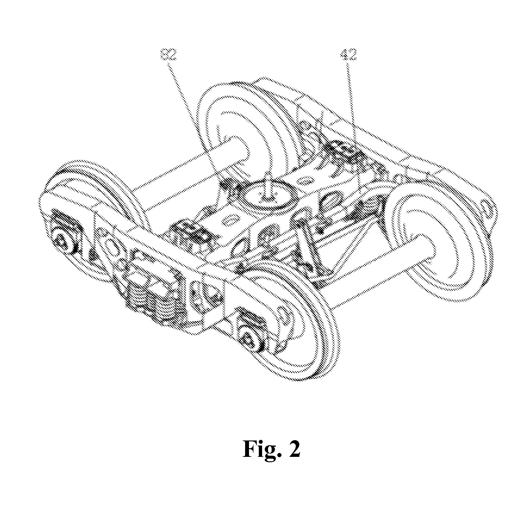
[0035]FIG. 1 is a structural diagram of the wheelset radial device of the invention arranged at the wheelset, FIG. 2 is a structural diagram of the bogie of the invention, FIG. 3 is a structural diagram of the sub-frame of the invention, FIG. 4 is a partial structural diagram of the end of the sub-frame of the invention, FIG. 5 is a structural diagram of the adapter of the invention, FIG. 6 is a structural diagram of the adapter of the invention in another direction, an...


PUM


Abstract

A sub-frame radial bogie comprises wheelsets, a side frame, a swing bolster, a wheelset radial device and a brake gear. Bearing adapters (41) forming the wheelset radial device are fixedly connected with the sub-frame (42) via pulling rivets (11), and each group of the bearing adapters (41) is bilaterally symmetrical in structure with a symmetry plane (A). The sub-frame (42) comprises an arm (51) and an end (52); a sub-frame connection hole (61) is arranged on the end (52); transverse positioning bosses (73) are arranged on the bearing adapters (41); and an arc groove (75) and symmetrical sub-frame connection holes (71) are arranged on a connection base (72). The bearing adapters use the same standard structure, hence, the more precise design and machining can be realized, and the cost is reduced, and meanwhile, the maintenance technique of the sub-frame is improved, and the maintenance cost is reduced.

Description

FIELD OF THE INVENTION[0001]The invention belongs to the railway transport equipment design and manufacturing field, in particular to the railway freight car bogie design and manufacturing field, and particularly relates to a sub-frame radial bogie for rolling stock.DESCRIPTION OF THE RELATED ART[0002]The bogie is a common structure of a railway freight car. For the railway freight car bogie, shear rigidity of the bogie is an important parameter affecting straight line operation stability thereof and can directly impact critical speed of hunting instability, operation stability and derailment safety of a rolling stock. Meanwhile, flexural rigidity is also an important parameter affecting curving performance of the bogie and can directly impact wheel wear rate and wheel-track force.[0003]Before the twenty-first century, the freight car bogies mainly comprised common three-piece bogie and welded bogies. Despite the advantages of simple structure and convenient manufacturer and mainten...

Claims


Application Information

Patent Timeline
IPC IPC(8): B61F5/04
CPCB61F5/04B61F5/38B61F5/28
Inventor DENG, TAOPAN, SHUPINGWANG, AIMINWANG, PUWANG, YUNGUILI, HENGLIZHANG, XIANFENGLUO, HANJIANGZHU, JIZHOU, ZONGQUANLIU, CHENGYONG
Owner CRRC MEISHAN
Why Eureka
Try Eureka