Gear unit for a compound transmission

Inactive Publication Date: 2015-07-30
ZF FRIEDRICHSHAFEN AG
View PDF13 Cites 9 Cited by
  • Summary
  • Abstract
  • Description
  • Claims
  • Application Information

AI Technical Summary

Benefits of technology

[0007]It is an object of the present invention to provide a transmission unit for a compound trans

Problems solved by technology

Further, transmissions in utility vehicles of this type usually require small geometric ratio steps betwe

Method used


Image

  • Gear unit for a compound transmission
  • Gear unit for a compound transmission
  • Gear unit for a compound transmission

Examples


first embodiment

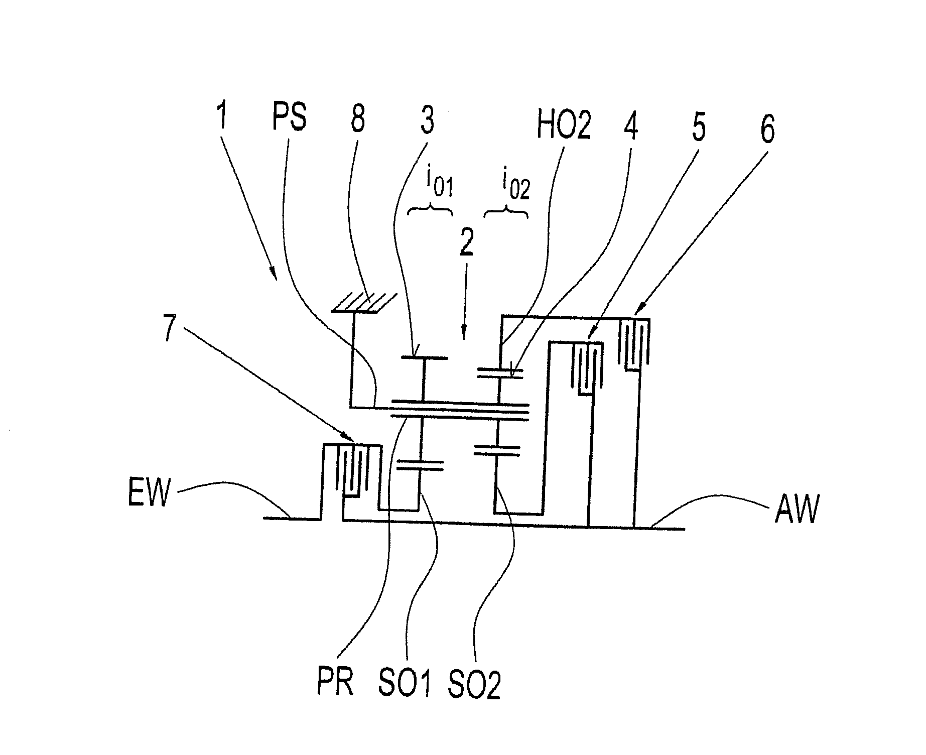
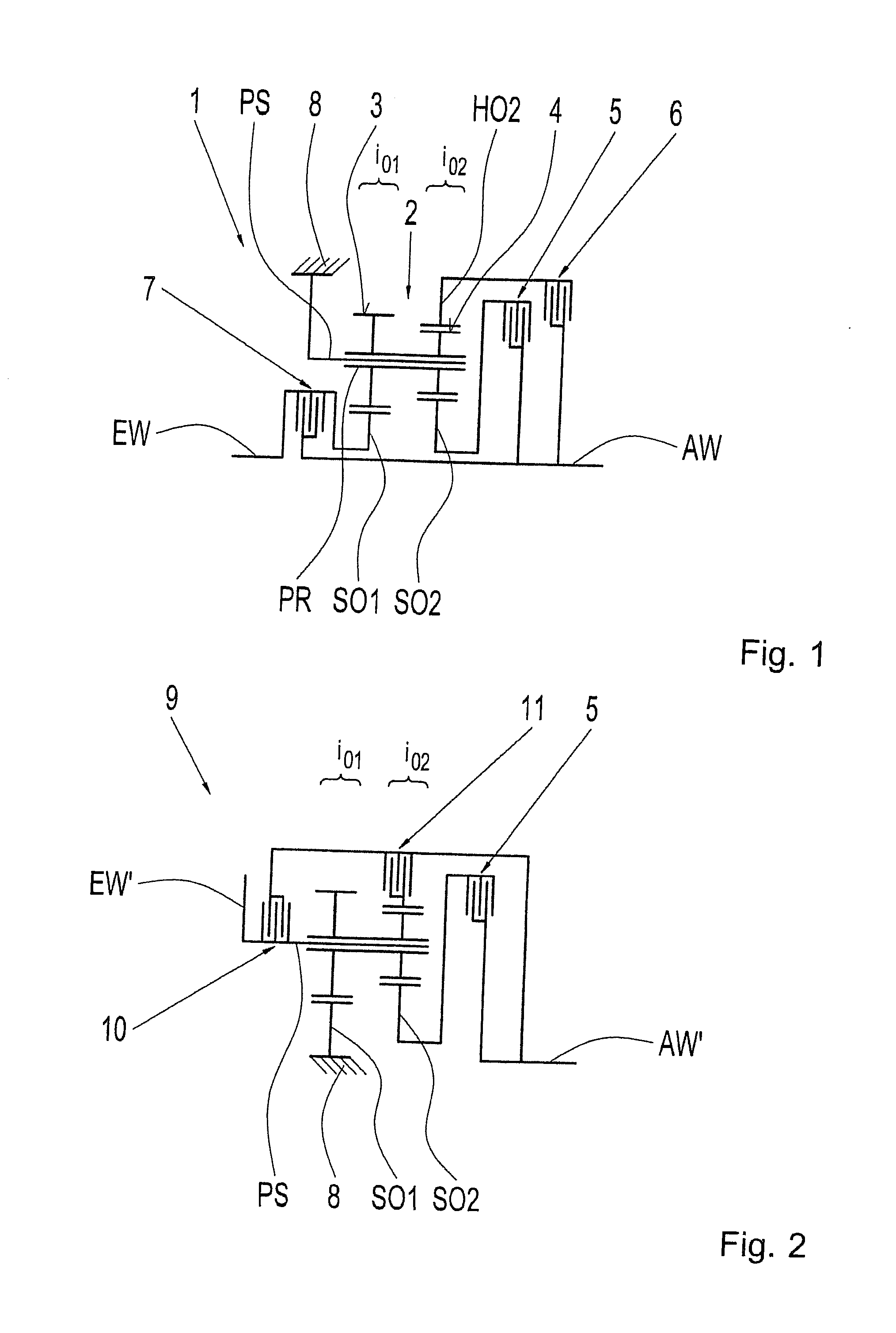
[0034]FIG. 1 shows a schematic view of a gear unit 1 corresponding to the invention, this gear unit 1 in the installed condition preferably forms part of a compound transmission of an agricultural or municipal utility vehicle, for example a tractor.

[0035]As will be seen from FIG. 1, the gear unit 1 comprises a planetary stage 2 which has a first sun gear SO1, a second sun gear SO2, a ring gear HO2, and a planet carrier PS. The planet carrier PS guides a plurality of planet gears PR, only one of which is presently shown. In each instance, the planet gears PR are rotatably mounted on the planet carrier PS and have in each instance two toothings 3 and 4 which are arranged axially adjacent to one another. Each of the planet gears PR meshes at its first toothing 3 with the radially inner first sun gear SO1, whereas meshing engagements with the radially inner, second sun gear SO2 and the radially circumscribing ring gear HO2 are produced via the second toothing 4. To this extent, the plan...

third embodiment

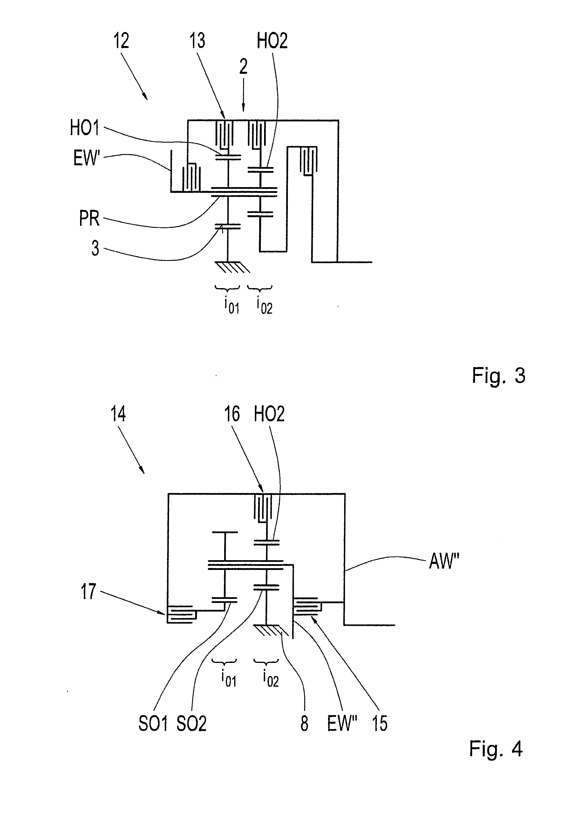
[0044]Further, FIG. 3 shows a schematic view of a gear unit 12 corresponding to the invention, this construction according to FIG. 3 substantially corresponds to the variant according to FIG. 2. One of the only difference is that in addition to ring gear HO2 there is also provided a first ring gear HO1, which meshingly engages with planet gears PR by toothing 3 and further can be coupled with the output shaft AW′ by a load shifting element 13. Consequently, an additional realizable transmission ratio is provided by this additional component of the planetary stage 2, and this additional transmission ratio defines a forward speed with overdriving of a rotational movement on output shaft AW′ for both possible stationary ratios i01 and i02 relative to one another.

[0045]FIG. 4 shows a schematic view of a gear unit 14 according to a fourth possible embodiment of the invention. In this case, in contrast to the variants according to FIGS. 1 to 3, the second sun gear SO2 is permanently coupl...


PUM


Abstract

A gear unit for a compound transmission has a planetary stage that couples an input and an output shaft for different transmission ratios. The planetary stage includes a sun gear, a ring gear and planet gears rotatably supported at a planet carrier. The planet gears have a region with two different toothings arranged axially offset with respect to an axis of rotation of the planetary stage. A meshing engagement with a first sun gear and/or a first ring gear is produced via the first toothing. The planet gears mesh at the second toothing with a second sun gear and/or a second ring gear, and one component of the planetary stage is connected to the input shaft to be fixed with respect to rotation and one component is fixed at a housing, while the rest of the components can be coupled with the output shaft, respectively.

Description

BACKGROUND OF THE INVENTION[0001]1. Field of the Invention[0002]The invention is directed to a gear unit for a compound transmission having a planetary stage by which an input shaft and an output shaft can be coupled with one another to realize different transmission ratios, wherein the planetary stage comprises at least one sun gear, at least one ring gear, and at least one planet carrier guiding a planet gear.[0003]2. Description of the Related Art[0004]Compound transmissions are used inter alia for agricultural and municipal utility vehicles to achieve large speed ranges at a reasonable cost. Thus the very broad spectrum of duties of an agricultural or municipal utility vehicle, e.g., the performance of work in fields and transportation, results in a wide variety of driving ranges which requires a correspondingly large spread between a slowest speed and a fastest speed. Further, transmissions in utility vehicles of this type usually require small geometric ratio steps between the...

Claims


Application Information

Patent Timeline
IPC IPC(8): F16H3/46
CPCF16H3/46F16H2200/2097F16H2200/2007F16H2003/447F16H3/663F16H2200/0034F16H2200/0039F16H2200/2038F16H2200/2041F16H37/042
Inventor HIMMELSBACH, RAPHAELWECHS, MICHAELGRAD, KARLBECK, STEFANRATTAY, MARTIN
Owner ZF FRIEDRICHSHAFEN AG
Why Eureka
Try Eureka