Method and device for restoring a light signal

a light signal and light signal technology, applied in the field of light signal restoration, can solve the problem that it is no longer possible to obtain color transitions perceived as continuous, and achieve the effect of increasing the fineness of colorimetric coordinate encoding, small brightness steps, and contributing to the fineness of brightness steps

Inactive Publication Date: 2005-06-28
CENT SCI & TECHN DU BATIMET
View PDF6 Cites 6 Cited by
  • Summary
  • Abstract
  • Description
  • Claims
  • Application Information

AI Technical Summary

Benefits of technology

[0012]In this way, a resultant light signal (the third light signal) is obtained which can present brightness values within a third set of discrete values substantially covering the first dynamic brightness range with brightness steps substantially equal to the second step value. If two video projectors are used, accepting digital data encoded over more than eight bits as an input, each of the first and second light signals may have a brightness value encoded over at the most eight bits. The result of this is that provision can be made that the number N of bits encoding the colorimetric coordinates of the light signal be, at most, equal to sixteen (N=16). This amounts to increasing the fineness of the encoding of the colorimetric coordinates by circumventing the limit imposed by the technology of the video cards and of the video projectors. Of course, the number N can be further increased by using other video projectors. The invention therefore makes it possible to generate a light signal with brightness values belonging to a set of discrete values covering a high dynamic brightness range with small brightness steps. In other words, the first light signal generated in step a) contributes to the dynamic range of the third signal, and the second signal generated in step b) contributes to the fineness of the brightness steps of this third signal. The principle of the invention consists of a new application of the property that the brightness has of being an additive quantity.

Problems solved by technology

On the other hand, this higher dynamic range would be covered by correlatively higher brightness steps, substantially equal to 100 cd / m2, which would no longer make it possible to obtain color transitions perceived overall as continuous.
This drawback is associated with the technology of video cards which are currently used for and in the video projectors, and which process digital input data encoded over at the most 8 bits.

Method used


Image

  • Method and device for restoring a light signal
  • Method and device for restoring a light signal
  • Method and device for restoring a light signal

Examples


Embodiment Construction

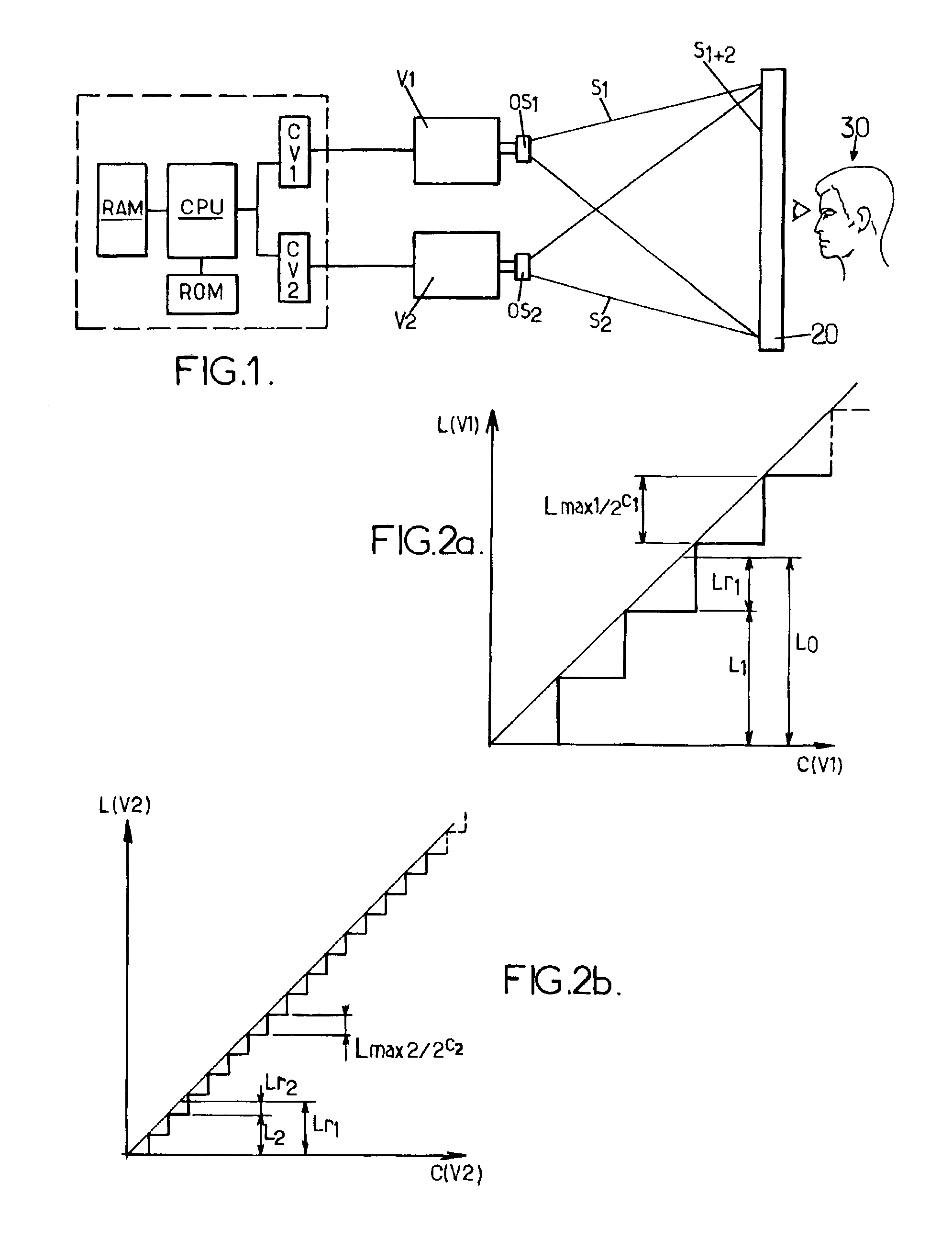
[0025]The principle of the invention is described below by considering first of all the simple case of a gray-level colorimetric system. In such a colorimetric system, a light signal is defined by one and only one colorimetric coordinate which corresponds to a brightness value, hereinafter called L0, associated with the only component of the light signal in this system. Note that it is easy to pass from a trichromatic system such as the RGB system to a gray-level system by applying the same command to the three R, G and B components such that they are always at identical levels. Moreover, it is considered that the behavior of the device is linear, that is to say that variations of the input command result in corresponding variations of the brightness values generated.

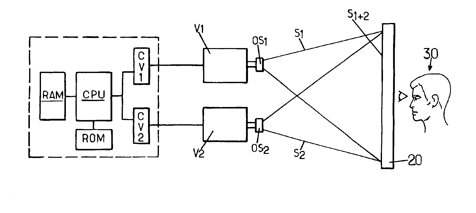
[0026]In FIG. 1, a device according to the invention comprises a first video projector V1 having a particular maximum light flux F1 and at least a second video projector V2 having a particular maximum light flux F2, suc...


PUM


Abstract

A method for restoring a light signal from digital data defining a colorimetric coordinate of the light signal in a specific colorimetric system, comprises the step of generating a first light signal using a first light restoration unit, the step of generating a second light signal using a second light restoration unit, and the step of generating a third light signal obtained by superimposing the first and second light signals. The second light restoration unit covers a brightness dynamics less than the brightness dynamics covered by the first restoration light unit. The second light restoration unit has a brightness resolution finer than the first light restoration unit.

Description

TECHNICAL FIELD[0001]The present invention relates to a method of restoring a light signal from digital data defining at least one colorimetric coordinate of the light signal in a particular colorimetric system, each colorimetric coordinate being encoded over N data bits and corresponding to a brightness value associated with a particular component of the light signal in the colorimetric system.[0002]The invention relates to the field of digital imaging, and is applicable to any type of digital light restoration unit. The invention is described below in its application to a digital light restoration unit operating by optical projection of an image onto a screen. Such a unit is called a video projector. However, this choice is not limiting, and the invention is also applicable, in particular, to a digital light restoration unit operating by means of a display on an electronic screen of the CRT (Cathode Ray Tube), liquid crystal, plasma or other type.BACKGROUND OF THE INVENTION[0003]A...

Claims


Application Information

Patent Timeline
Patent Type & Authority Patents(United States)
IPC IPC(8): H04N9/31G03B21/60G03B21/00H04N5/74
CPCH04N9/3197H04N9/3185H04N9/3147
Inventor DAVID, LAURENTCARRE, SAMUEL
Owner CENT SCI & TECHN DU BATIMET
Why Eureka
Try Eureka