Hydraulic control device

a control device and hydraulic technology, applied in solar heat devices, solar heat collector controllers, lighting and heating apparatuses, etc., can solve the problems of high mechanical load of hydraulic medium, large waste of solenoid actuating primary energy, and complex control devices, etc., to achieve fair costs, small movement steps, and energy saving

Inactive Publication Date: 2009-09-24
HAWE HYDRAULIK SE
View PDF4 Cites 6 Cited by
  • Summary
  • Abstract
  • Description
  • Claims
  • Application Information

AI Technical Summary

Benefits of technology

[0007]It is an object of the invention to provide a hydraulic control device and a method for moving at least one hydraulic consumer allowing to control hydraulic consumers in extremely small movement steps in a structurally simple, fair costs and energy saving fashion.

Problems solved by technology

This short time or small opening degree needs powerful solenoids and a complicated control device.
Moreover, a lot of solenoid actuating primary energy is wasted, and the hydraulic medium is mechanically highly loaded.
Small movements of a hydraulic consumer, e.g. only some millimetres, until now, cannot be realised satisfactorily with conventional technologies.
As large numbers of solar panels in most cases in solar power plants are controlled by discrete control devices, the above-mentioned complicated structures and the sophisticated control technology result in a cost factor which cannot be tolerated.
In addition, such control devices for solar panels contain an electrohydraulic control section which, of course, only should consume a fraction of the electric energy which is gained by the solar panel itself.
However, extremely weak solenoids normally are not apt to control extremely small movements of the hydraulic consumers.

Method used


Image

  • Hydraulic control device
  • Hydraulic control device
  • Hydraulic control device

Examples


Embodiment Construction

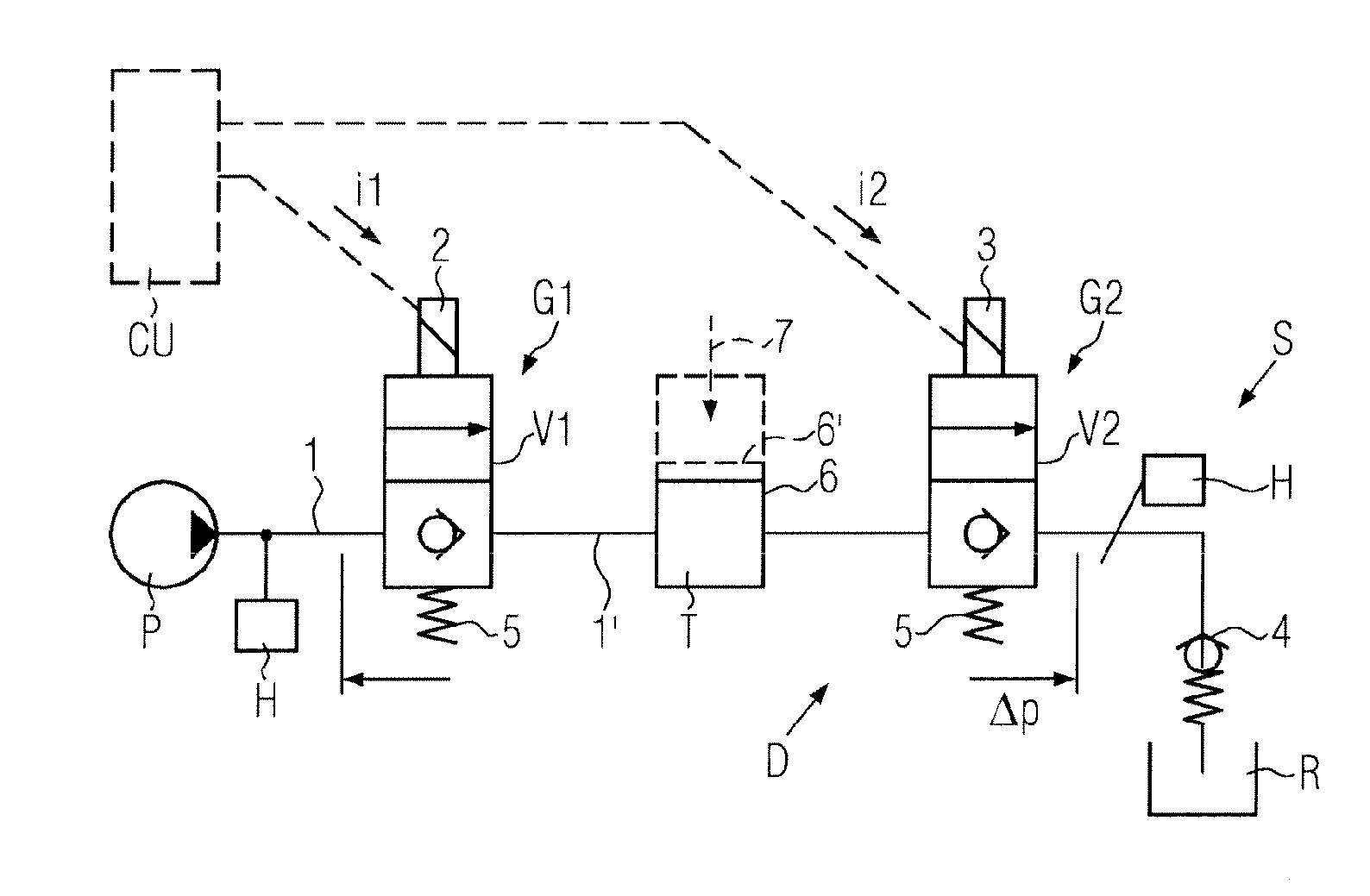
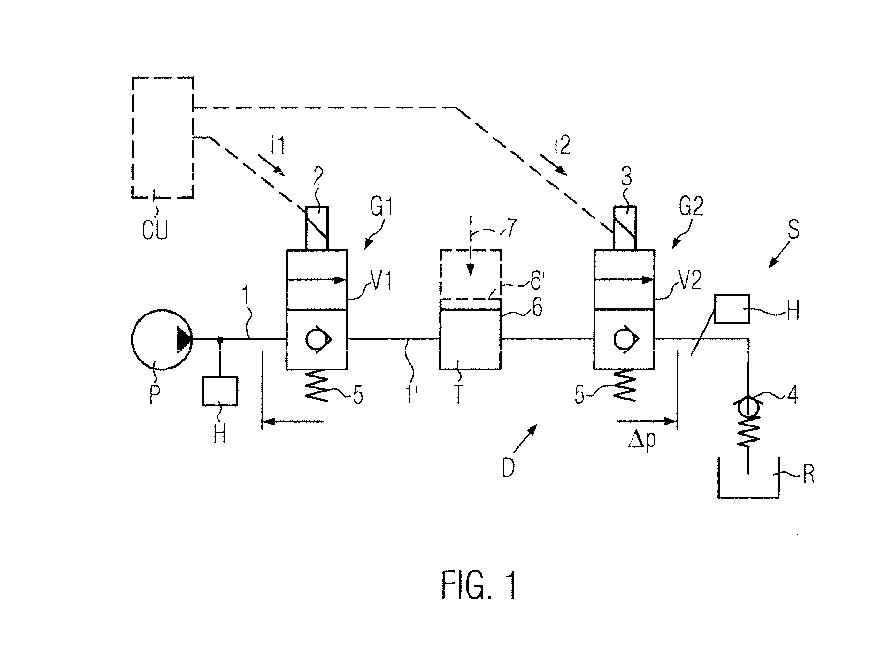
[0023]A hydraulic control device S schematically shown in FIG. 1 among others is designed such that a hydraulic consumer H can be controlled to carry out minimally small movement steps by means of a hydraulic medium which at least can be compressed within given limits. A respective small movement actuation step or several consecutive movement steps of the hydraulic consumer H either is controlled by discharging a hydraulic medium dose from the hydraulic consumer or by feeding the hydraulic medium dose into the consumer, with the hydraulic medium dose being precisely measured solely by using the inherent compressibility of the hydraulic medium.

[0024]The hydraulic control device S e.g. comprises a pump P as a pressure source (or a pressure accumulator, not shown), which source feeds hydraulic medium into a line 1. The line 1 either is a supply line or a discharge line or a bypass line to which the hydraulic consumer H is connected. A dosing device D is included in the hydraulic contro...


PUM


Abstract

A hydraulic control device for moving at least one hydraulic consumer comprises at least one supply line, a discharge line or bypass line to which the hydraulic consumer is connected, and at least one pressure source and, optionally, a directional control valve. The line contains a dosing device for measuring a hydraulic medium dose by using a given compressibility of the hydraulic medium. The measured hydraulic medium dose either is supplied from the dosing device into the hydraulic consumer connected downstream or is discharged from the hydraulic consumer connected upstream into the dosing device. The dosing device comprises from upstream to downstream in series first and second blocking members which respectively can be switched into a leakage-free blocking position and into a through flow position, and a dead space between the blocking members. For dosing the hydraulic medium dose the blocking members are switched several times alternatingly.

Description

BACKGROUND OF THE INVENTION[0001]This application claims the benefit under 35 USC 119 of European Patent Application No. 08005381.2, filed Mar. 20, 2008, the disclosure of which is incorporated herein by reference.[0002]Sometimes it is necessary in the field of high pressure hydraulic to control a hydraulic consumer to carry out extremely small movements only. In many cases, this hydraulic consumer is also controlled in a conventional fashion to carry out large movements, and if necessary, even independent of the current load. The mentioned small movements of the hydraulic consumer can be realised only with dedicated structures because of the conventional high working pressures of about 100 to 800 bar, e.g. by means of relatively large dimensioned solenoid valves or throttling valves which then are controlled to open for a very short time and / or very little. This short time or small opening degree needs powerful solenoids and a complicated control device. Moreover, a lot of solenoid...

Claims


Application Information

Patent Timeline
Patent Type & Authority Applications(United States)
IPC IPC(8): F24J2/38F24S50/20
CPCF15B11/08F15B11/128F15B11/13F15B2211/305F15B2211/30565F15B2211/3138F15B2211/8855F15B2211/31529F15B2211/31558F15B2211/35F15B2211/625F15B2211/765F15B2211/31511
Inventor HEUSSER, MARTINHUNDSCHELL, HILARIUSRUMENAP, SASCHA
Owner HAWE HYDRAULIK SE
Why Eureka
Try Eureka