Light emitting diode drive device, illumination device, in-vehicle cabin illumination device, and vehicle illumination device

a technology of light emitting diodes and drive devices, which is applied in the direction of electric variable regulation, process and machine control, instruments, etc., can solve the problems of structure complicating circuit configuration, and achieve the effect of reducing manufacturing costs, simplifying circuit configuration, and manufacturing with smaller manufacturing steps

Active Publication Date: 2013-01-29
PANASONIC CORP
View PDF28 Cites 6 Cited by
  • Summary
  • Abstract
  • Description
  • Claims
  • Application Information

AI Technical Summary

Benefits of technology

[0010]The present invention has been devised in view of the circumstances described above, and one object thereof is to provide a light emitting diode drive device for applying a direct-current voltage to a light source including a plurality of light emitting diodes connected in series to allow the light source to light up. This light emitting diode drive device can determine whether or not the light emitting diode, which lights up, is short-circuited with a simple circuit configuration as compared with a conventional light emitting diode drive device having circuitry for detecting voltages at a plurality of light emitting diodes. Moreover, this light emitting diode drive device can be manufactured with smaller manufacturing steps at lower manufacturing cost as compared with a conventional light emitting diode drive device including a plurality of voltage detection circuit sections. Another object of the present invention is to provide an illumination device, an in-vehicle cabin illumination device and a vehicle illumination device each employing the light emitting diode drive device.

Problems solved by technology

This structure complicates a circuit configuration.Patent Document 1: Japanese Unexamined Patent Publication No.

Method used


Image

  • Light emitting diode drive device, illumination device, in-vehicle cabin illumination device, and vehicle illumination device
  • Light emitting diode drive device, illumination device, in-vehicle cabin illumination device, and vehicle illumination device
  • Light emitting diode drive device, illumination device, in-vehicle cabin illumination device, and vehicle illumination device

Examples


first embodiment

[0022]A circuit configuration and operations of a light emitting diode drive device A according to the present embodiment will be described with reference to FIGS. 1 through 6.

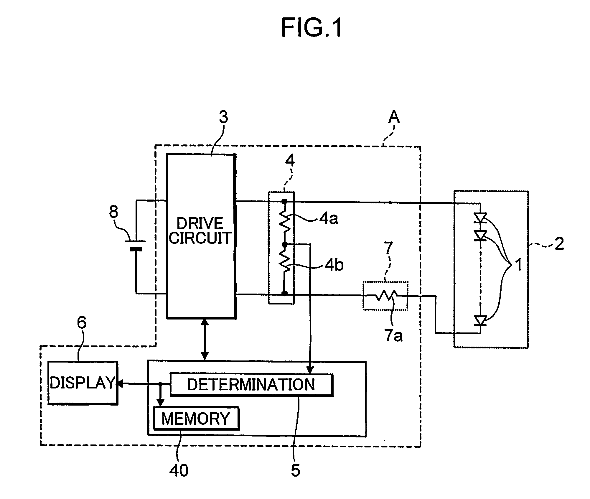
[0023]First, the basic circuit configuration of the light emitting diode drive device A according to the present embodiment is described with reference to FIG. 1.

[0024]The light emitting diode drive device A according to the present embodiment includes a drive circuit section 3 that converts electric power supplied from a power supply 8 into a direct-current voltage and outputs the direct-current voltage, a voltage detection circuit section 4 that detects a voltage across a light source 2 including a plurality of light emitting diodes 1 connected in series, a malfunction determination circuit section 5 that determines whether or not the light emitting diode 1, which lights up, is short-circuited, based on the voltage detected by the voltage detection circuit section 4, a display section 6 that displays the res...

second embodiment

[0048]As shown in FIG. 6, a light emitting diode drive device A according to the present embodiment is different from the light emitting diode drive device A according to the first embodiment in a point that a flyback converter 3b including a flyback transformer 28 is provided in place of the drive circuit section 3. In the present embodiment, the remaining configuration is similar to that described in the first embodiment. In the present embodiment, constituent members identical with those in the first embodiment are denoted with the identical reference signs, and therefore the description thereof will not be given.

[0049]A configuration and operations of the flyback converter 3b are described herein below with reference to FIG. 6.

[0050]The flyback converter 3b includes a flyback transformer 28 that includes a power supply-side wire 26 wound around a core (not shown) with a first end thereof connected to a high pressure side of a power supply 8 which is a direct-current power supply...

third embodiment

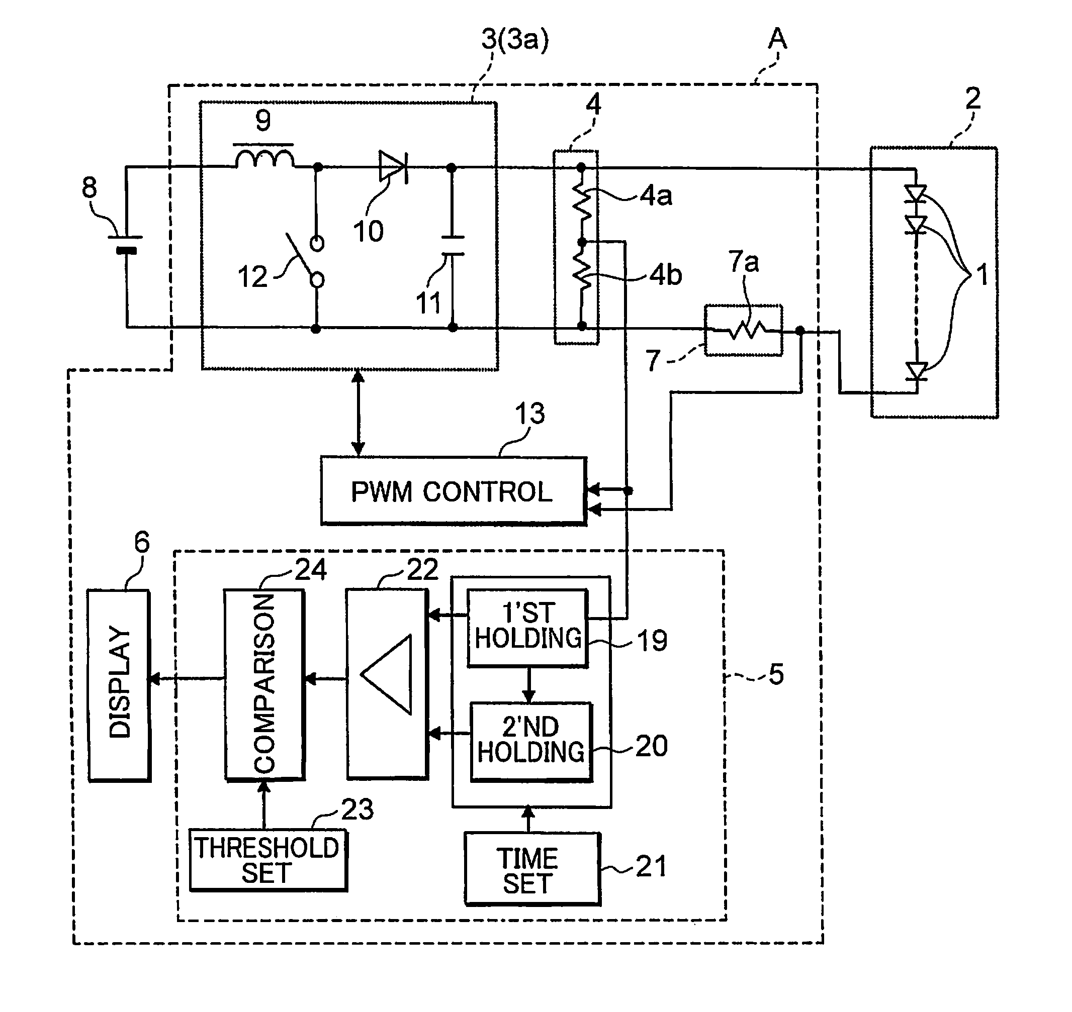
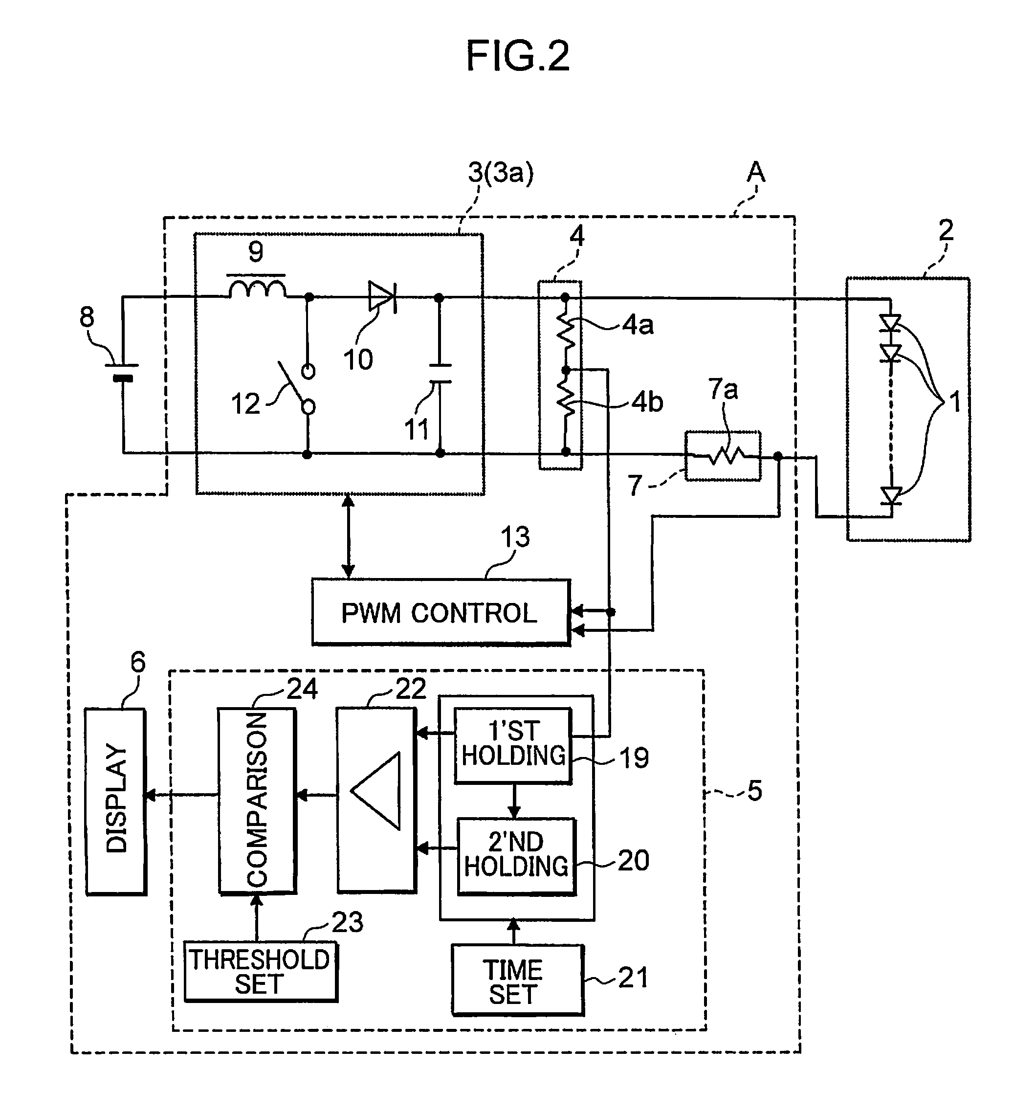
[0055]As shown in FIG. 7 and FIG. 8, a light emitting diode drive device according to the present embodiment is different from the light emitting diode drive device according to the first embodiment in points that a microcomputer 25 includes a PWM control circuit section 13, a malfunction determination circuit section 5 and a memory circuit section 40 and the memory circuit section 40 is a flash memory. In the present embodiment, the remaining configuration is similar to that described in the first or second embodiment. In the present embodiment, constituent members identical with those in the first or second embodiment are denoted with the identical reference signs, and therefore the description thereof will not be given.

[0056]The microcomputer 25 includes an output interface 36. A PWM control signal is generated by a PWM control signal generation circuit section 17 of the PWM control circuit section 13, and is output to a driver control section 18 via the output interface 36.

[0057...


PUM


Abstract

A light emitting diode drive device includes a drive circuit section that applies a direct-current voltage to a light source including a plurality of light emitting diodes connected in series to allow the light source to light up, a voltage detection circuit section that detects a voltage across the light source, and a malfunction determination circuit section that determines that the light emitting diode is short-circuited when the voltage detection circuit section detects a voltage drop and a potential between the voltage before being dropped and the voltage after being dropped is equal to or more than a predetermined threshold value. Thus, it is possible to detect a fact that a light emitting diode, which lights up, is short-circuited or is not short-circuited, with a simple circuit configuration.

Description

TECHNICAL FIELD[0001]The present invention relates to a light emitting diode drive device, as well as an illumination device, an in-vehicle cabin illumination device and a vehicle illumination device each employing the light emitting diode drive device.BACKGROUND ART[0002]As compared with an incandescent bulb, a light emitting diode is long in service life and excellent in responsivity of light emission upon reception of electric power because of light emission principles thereof. Moreover, a light emitting diode can be used in a compact and stereoscopic manner, and therefore is less susceptible to restrictions regarding a shape as an illumination device. Further, a light emitting diode can readily realize light emission of various colors without filters or the like. Accordingly, there have been proposed various illumination devices each including such a light emitting diode serving as a light source and various light emitting diode drive devices for supplying electric power to the ...

Claims


Application Information

Patent Timeline
Patent Type & Authority Patents(United States)
IPC IPC(8): B60L1/14H01L33/00H05B44/00
CPCH05B33/0815H05B33/0851H05B33/0893H05B45/58H05B45/10H05B45/38H05B45/385
Inventor NAGASE, HARUO
Owner PANASONIC CORP
Why Eureka
Try Eureka