Electronic Retrofit Controller for Hydraulically Adjusted Printing Press

a technology of hydraulic adjustment and retrofit controller, which is applied in the direction of gearing, dynamo-electric converter control, instruments, etc., can solve the problems of inaccuracy of adjustments, slow adjustment times, and hydraulic controls limited to a relatively large minimum adjustment, so as to achieve faster calibration and reduce the effect of adjustment time and adjustment accuracy

Inactive Publication Date: 2010-08-05
INNOVATIVE MOTOR CONTROLS
View PDF43 Cites 8 Cited by
  • Summary
  • Abstract
  • Description
  • Claims
  • Application Information

AI Technical Summary

Benefits of technology

[0004]An example embodiment of the present invention include a motor and assembly that attaches to existing hydraulic actuators and replaces the hydraulic power operating the actuator with electrical power. The electrically-powered actuators can be operated simultaneously with each other, enabling faster calibration than hydraulically powered actuators, which must be operated individually. Also, the electrically-powered actuators are more accurate than the hydraulic-powered actuators because they can take smaller steps than the hydraulic-powered actuators and because they do not overshoot, i.e., tend to continue actuating after the control signal ends. These benefits of electrically-powered actuators significantly reduce the time required to calibrate the register of a color printing press, thereby increasing the time available to run a printing job and decreasing the amount of waste generated.

Problems solved by technology

The hydraulic systems cause two problems: inaccurate adjustments and slow adjustment times. The inaccuracies are caused by continued movement of the hydraulic actuator after a control input has ceased.
Also, the hydraulic controls are limited to a relatively large minimum adjustment such that an operator often has to overshoot an adjustment in one direction to “dial in” the adjustment in the opposite direction.
The slow adjustment times are caused by incapability of the hydraulic supply system to simultaneously actuate several different actuators.
Because the printing press is printing paper during the adjustment period after start-up, the printing press is generating waste until the printer is calibrated.
Delays in calibration caused by the inaccuracies and slow adjustment times described above are significant contributors to the amount of generated waste.
Again, the delays in calibration result in significant waste.

Method used


Image

  • Electronic Retrofit Controller for Hydraulically Adjusted Printing Press
  • Electronic Retrofit Controller for Hydraulically Adjusted Printing Press
  • Electronic Retrofit Controller for Hydraulically Adjusted Printing Press

Examples


Embodiment Construction

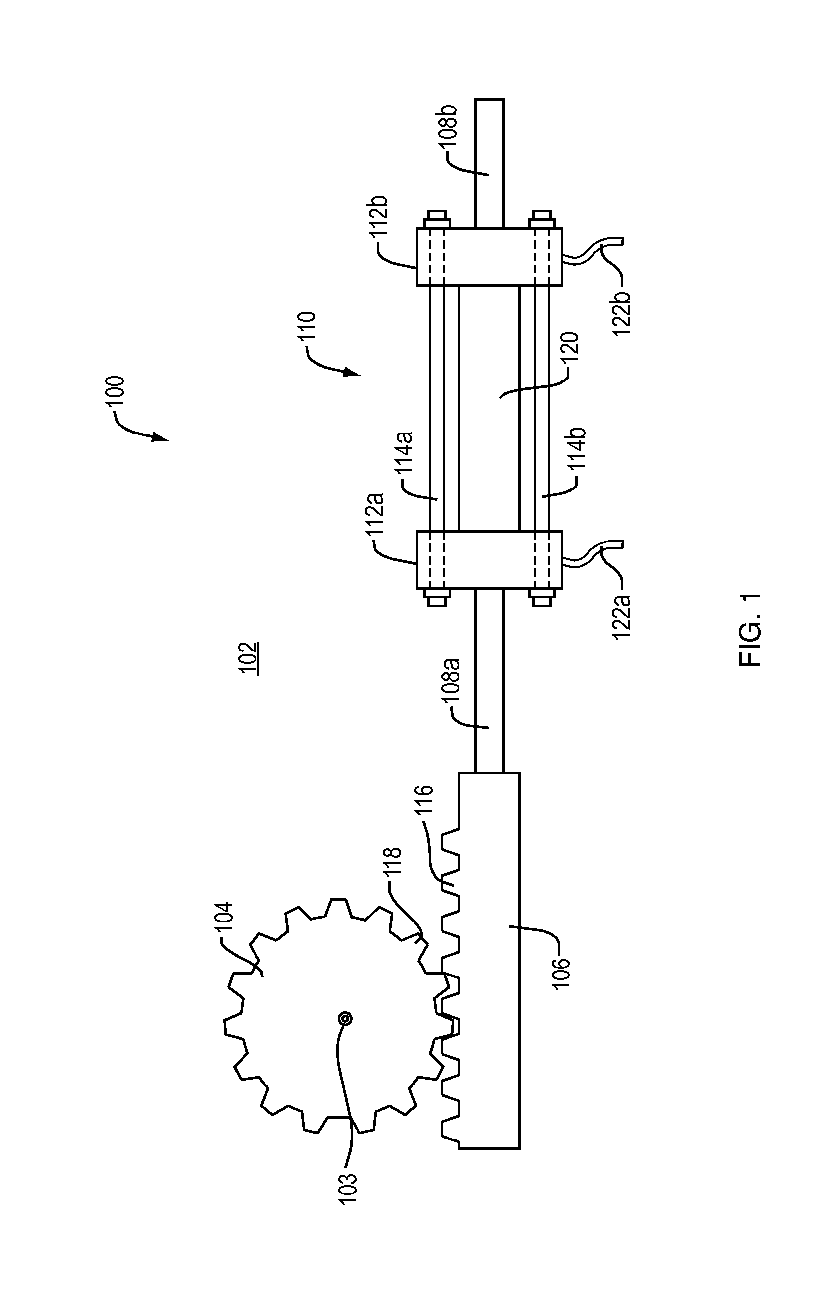
[0013]A description of example embodiments of the invention follows. FIG. 1 shows a prior art hydraulically actuated printing press adjustment 100. A gear 104 is mounted to a frame member 102 of a printing press and the axis of rotation 103 of the gear 104 is connected to an adjustment mechanism (not shown) of the printing press. For example, gear 104 may be connected to a mechanism that adjusts one of lateral or circumferential position of a printing press cylinder (not shown). The gear has teeth 118 (partially shown), which mesh with corresponding gears 116 on a rack 106. An end of the rack 106 is attached to a hydraulic actuator shaft 108a. The hydraulic actuator shaft 108a passes through a housing 110 and an opposite end of the hydraulic actuator shaft 108b extends from the opposite end of the housing 110. The housing includes a cylinder wall 120 and two end caps 112a, 112b. The end caps 112a, 112b are pressed against the ends of cylinder wall 120 by threaded rods 114a, 114b. No...


PUM

PropertyMeasurementUnit
movementaaaaaaaaaa
poweraaaaaaaaaa
hydraulic poweraaaaaaaaaa

Abstract

A retrofit kit for a printing press adjustment hydraulic actuator. The hydraulic actuator is maintained to benefit from its mounting position and alignment, but the hydraulic fluid is removed. A hydraulic actuator shaft is attached to a mechanism that converts the rotary motion of an electric motor to linear motion. The electric motor provides faster and more accurate control of the hydraulic actuator shaft than the hydraulic fluid, providing for faster adjustment of the printing press.

Description

RELATED APPLICATIONS[0001]The present application claims the benefit of a prior U.S. Provisional Application No. 61 / 147,820, filed Jan. 28, 2009. The entire teachings of the above application are incorporated herein by reference.BACKGROUND OF THE INVENTION[0002]Some printing presses, such as the Goss “Metro Color” printing press, use hydraulic actuators to adjust the circumferential and lateral registers of each color print roller on the press. The hydraulic systems cause two problems: inaccurate adjustments and slow adjustment times. The inaccuracies are caused by continued movement of the hydraulic actuator after a control input has ceased. Also, the hydraulic controls are limited to a relatively large minimum adjustment such that an operator often has to overshoot an adjustment in one direction to “dial in” the adjustment in the opposite direction. The slow adjustment times are caused by incapability of the hydraulic supply system to simultaneously actuate several different actua...

Claims


Application Information

Patent Timeline
Patent Type & Authority Applications(United States)
IPC IPC(8): H02K7/116F16H25/20H05K13/00H02P8/00H02K37/00B41F1/26
CPCB41F13/14Y10T29/49002Y10T74/18576
Inventor DAVIS, DALE R.
Owner INNOVATIVE MOTOR CONTROLS
Why Eureka
Try Eureka