Pressure limiting valve and alternative method for testing a backflow preventer using the same

a technology of pressure limiter and backflow preventer, which is applied in the direction of diaphragm valve, engine diaphragm, valve operating means/release devices, etc., can solve the problem of limiting the maximum pressure delivered to the low pressure gauge, and achieve the effect of facilitating the opening and closing of the outlet and ensuring the seal

Active Publication Date: 2015-07-30
FRAHM II LAWRENCE L
View PDF10 Cites 11 Cited by
  • Summary
  • Abstract
  • Description
  • Claims
  • Application Information

AI Technical Summary

Benefits of technology

[0029]In an alternative embodiment, the pressure limiting valve has a low pressure gauge configured to measure the operability of a backflow preventer having a line pressure relatively higher than the maximum rating of the low pressure gauge. In this embodiment, the valve similarly includes a valve body having an inlet configured to statically couple to the backflow preventer and an outlet configured to couple to the low pressure gauge. An upper and a lower chamber formed from an interior portion of the valve body are generally separated from one another by a flexible rubber diaphragm, yet fluidly coupled via a conduit. To protect the low pressure gauge from over-pressurization, a relief valve may be fluidly coupled thereto. The relief valve preferably has a release point relatively lower than the maximum PSI rating of the low pressure gauge. Furthermore, a needle valve having a movable stem may selectively fluidly couple the lower chamber to a drain to help pressurize the valve assembly before activating the pressure limiting valve.
[0030]In this embodiment, the valve assembly includes a pair of opposing springs disposed across opposite portions of the flexible diaphragm in respective upper and lower chambers. The springs are actuable via movement of the flexible diaphragm in response to pressure changes in the valve body. The first spring generally biases a closure disc in an open position relative to the outlet and the second spring generally opposes open movement of the closure disc by the first spring when the valve is not under pressure. Accordingly, the first spring compresses under pressure to permit the closure disc to seal the outlet when pressure in the valve body approximately reaches a maximum PSI rating of the low pressure gauge. This feature effectively limits the maximum pressure deliverable to the low pressure gauge. A seat positioned near the outlet and generally tapering downwardly away from the diaphragm permits deflection of the closure disc thereover to form a better seal. A diaphragm retainer disposed across at least a portion of the planar surface of the diaphragm and influenced by movement of the first and second springs may additional help facilitate the opening and closing of the outlet.

Problems solved by technology

Alternatively, the spring compresses under pressure to permit the closure disc to seal the outlet when pressure in the valve body approximately reaches a maximum PSI rating of the low pressure gauge, thereby limiting the maximum pressure deliverable to the low pressure gauge.

Method used


Image

  • Pressure limiting valve and alternative method for testing a backflow preventer using the same
  • Pressure limiting valve and alternative method for testing a backflow preventer using the same
  • Pressure limiting valve and alternative method for testing a backflow preventer using the same

Examples


Embodiment Construction

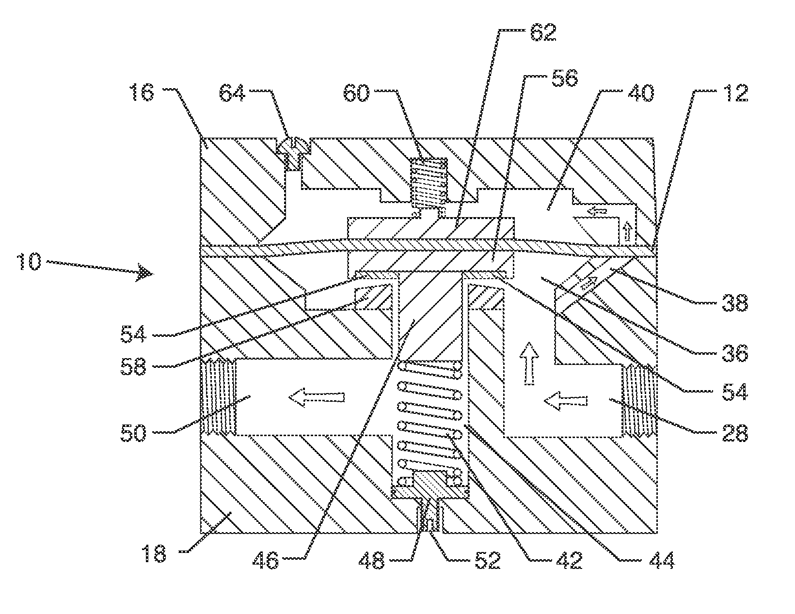
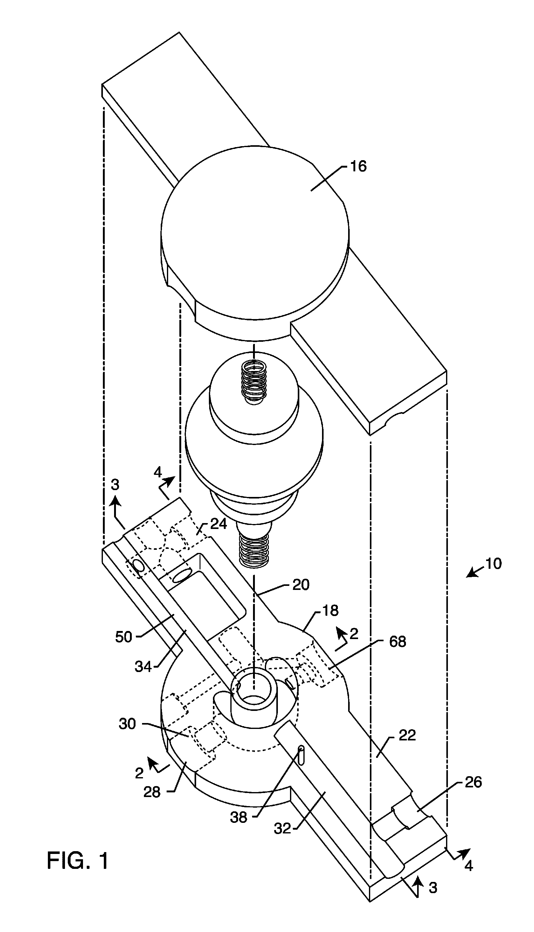
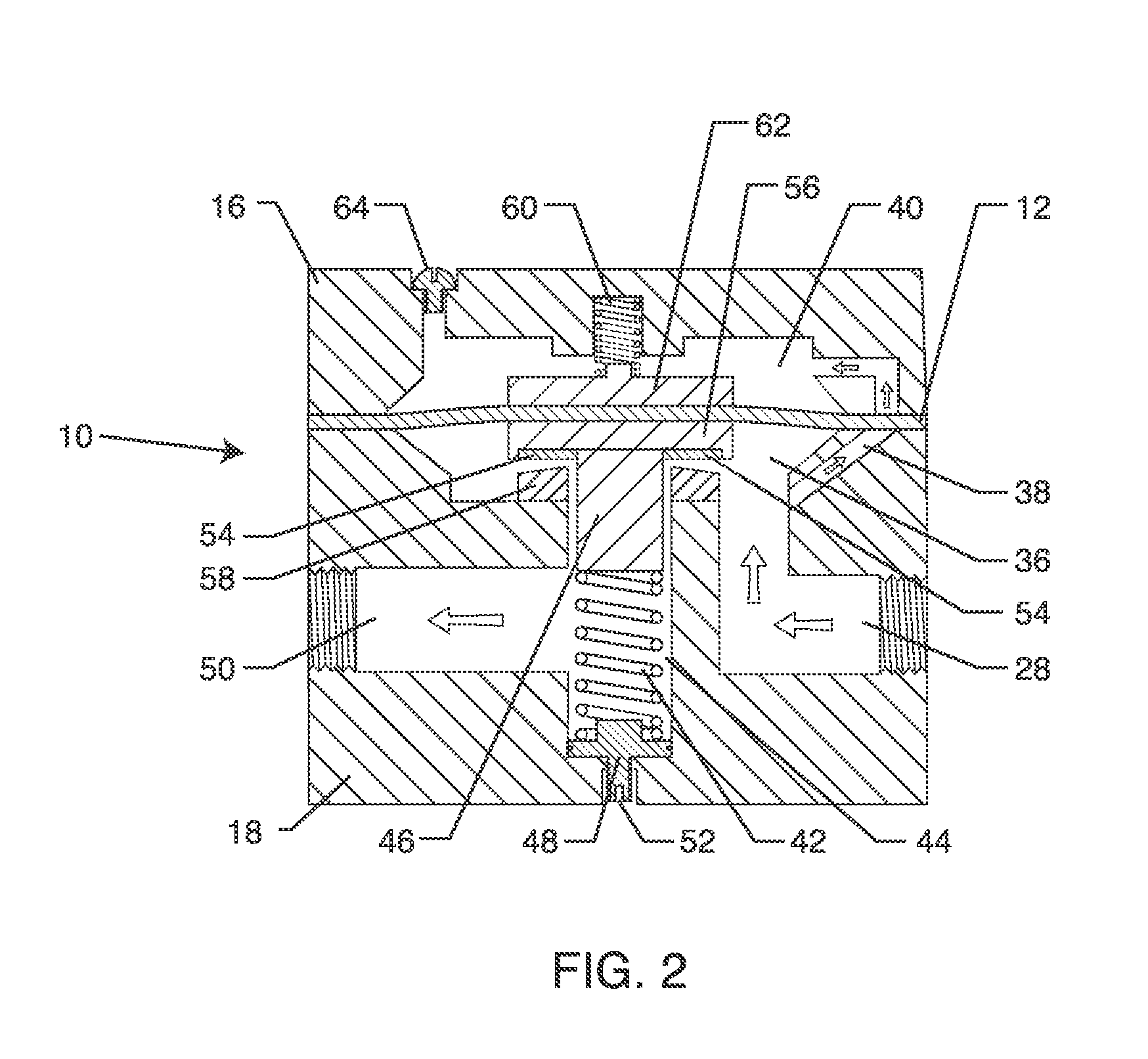
[0074]As shown in the exemplary drawings for purposes of illustration, the present disclosure for a pressure limiting valve is referred to generally by the reference numeral 10. The valve 10 may be used to protect different types of pressure gauges from over-pressurization, while allowing the pressure gauge to function normally within design operating ranges in either ascending or descending indications. Such a pressure limiting valve 10 incorporates a flexible diaphragm 12 biased between a pair of opposing springs, as generally shown and described in more detail with respect to FIGS. 2 and 4. Problems known in the art with respect to pressure gauges are inaccurate readings and damage resultant from over-pressurization. For example, when testing a backflow prevention device, it is desirable to use a low pressure gauge to take high accuracy readings on an otherwise high pressure system. A well known problem in the art is that the low pressure gauge is subject to damage in the event i...


PUM


Abstract

The pressure limiting valve has a low pressure gauge configured to measure the operability of a backflow prevention device having a line pressure relatively higher than the maximum PSI rating of the low pressure gauge. The valve body has an inlet statically coupled to a pressurized fluid source and an outlet coupled to the low pressure gauge. Upper and lower chambers fluidly coupled via a conduit are formed from an interior portion of the valve body and generally separated by a flexible diaphragm. A spring actuable via movement of the flexible diaphragm in response to pressure changes in the valve body biases a closure seat in an open position relative to the outlet when the valve body is not under pressure, and compresses under pressure to permit the closure seat to seal the outlet when pressure in the valve body reaches a maximum PSI rating of the low pressure gauge.

Description

BACKGROUND OF THE INVENTION [0001]The present invention relates to a pressure limiting valve and related method for testing the operability of a backflow preventer. More specifically, the present invention relates to a pressure limiting valve with opposing springs that limits the pressure of fluid deliverable to a low pressure gauge in applications for testing the operability of a backflow preventer having one or more check or relief valves located on high or low pressure systems.[0002]For decades, there have been local, state and federal health and safety regulations requiring the installation of valves known as backflow prevention devices on potable and non-potable water systems. The purpose of the backflow prevention device is to protect the main water distribution system from contamination or pollution that may originate from liquid backflow from lines attached to the distribution system as a result of very low or negative pressures. Normally, liquid in a water supply system is ...

Claims


Application Information

Patent Timeline
Patent Type & Authority Applications(United States)
IPC IPC(8): F16K15/06F16K7/12F16K37/00
CPCF16K15/066F16K7/12F16K37/0091Y10T137/7793Y10T137/0379F16K17/30E03C1/104Y10T137/7826F16K17/28
Inventor FRAHM, II, LAWRENCE L.
Owner FRAHM II LAWRENCE L
Why Eureka
Try Eureka