Supercharge Your Innovation With Domain-Expert AI Agents!

Device for testing application state of fiber reinforced plastic tape

a technology of fiber reinforced plastics and devices, applied in the field of devices for testing the application state of fiber reinforced plastic tape, can solve the problems of untested supply path, untested front and rear ends, and untested prepreg, so as to reduce testing expense and duration, and increase testing accuracy.

Active Publication Date: 2015-07-30
TORAY ENG CO LTD
View PDF4 Cites 8 Cited by
  • Summary
  • Abstract
  • Description
  • Claims
  • Application Information

AI Technical Summary

Benefits of technology

The present invention aims to provide a device that can automatically and quickly test the application state of multiple strips of fiber reinforced plastic tape affixed on a structure surface. The device comprises a relative movement component that keeps the distance between the observation component and the surface of the structure constant while relatively moving the observation site. The testing is done without relying on humans, increasing accuracy and reducing expense and duration.

Problems solved by technology

This test is sometimes performed automatically while the prepregs are being applied (see Japanese Patent No. 4,691,562 (Patent Literature 1) and Japanese Translation of PCT International Application Publication No. 2009-531715 (Patent Literature 2), for example), but uneven positioning of the front and rear ends where the prepreg is applied, or the adhesion of foreign matter that may occur due to problems along the supply path could not be tested for.
However, when the test object is an aircraft fuselage or the like, and dozens of prepreg layers are laminated, when the lamination is performed by continuously varying the direction of the prepreg fibers in various ways, such as when at a certain level the fibers are oriented longitudinally, then diagonally at the next layer, then laterally at the next layer, steps can be generated by the gaps between one strip of tape and the one underneath, for example, and consequently, in visual testing by a human, numerous problems may be encountered in terms of ensuring the tester has enough experience, speeding up how long the test takes, attaining good reproducibility in the test quality, and so forth.

Method used


Image

  • Device for testing application state of fiber reinforced plastic tape
  • Device for testing application state of fiber reinforced plastic tape
  • Device for testing application state of fiber reinforced plastic tape

Examples


Embodiment Construction

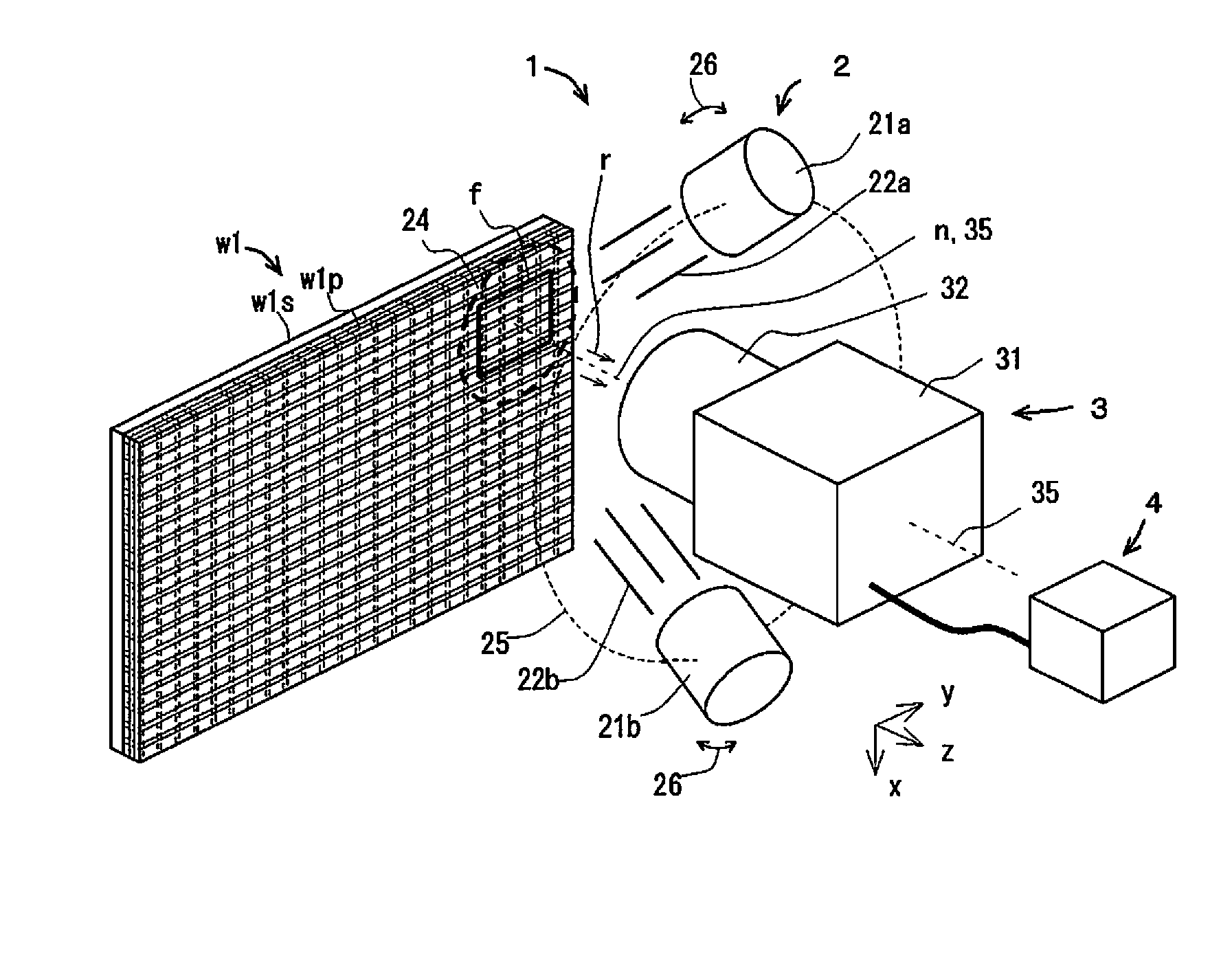
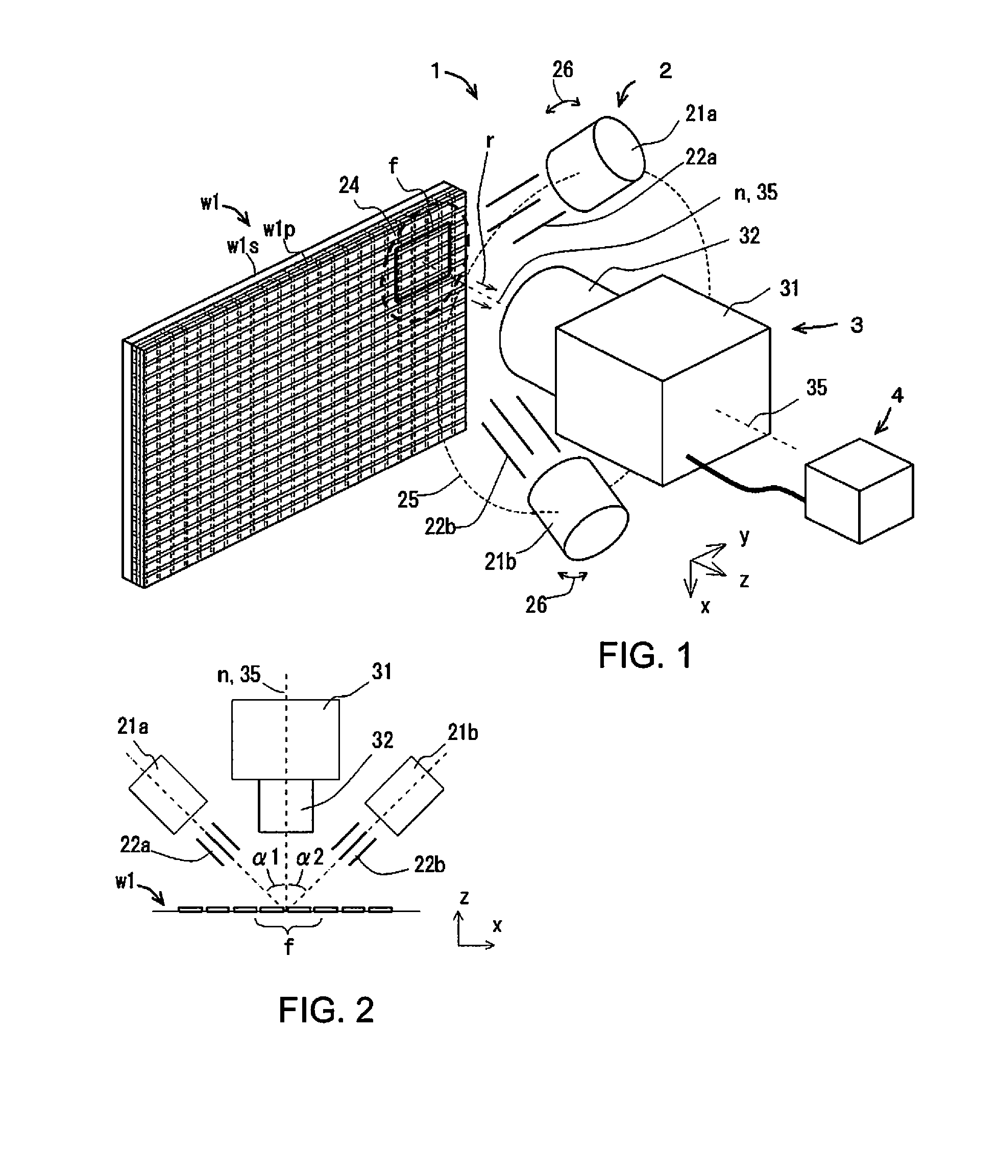
[0057]The device (hereinafter referred to as test device) pertaining to the present invention for testing the application state of fiber reinforced plastic tape (hereinafter also referred to simply as tape) will now be described through reference to FIG. 1. In the drawing, we will let the test region faces of the test object represent the X and Y directions, and let the tape thickness direction that is perpendicular to these directions represent the Z direction (the same applies hereinafter).

[0058]FIG. 1 is an oblique view of the simplified configuration of the test device pertaining to the present invention, and illustrates one embodiment of testing a structure w1 that is a flat test object (hereinafter referred to as the test object). This test object w1 is produced by laminating a number of layers of fiber reinforced plastic tape w1p over the surface of a structure w1s while varying the direction of the tape.

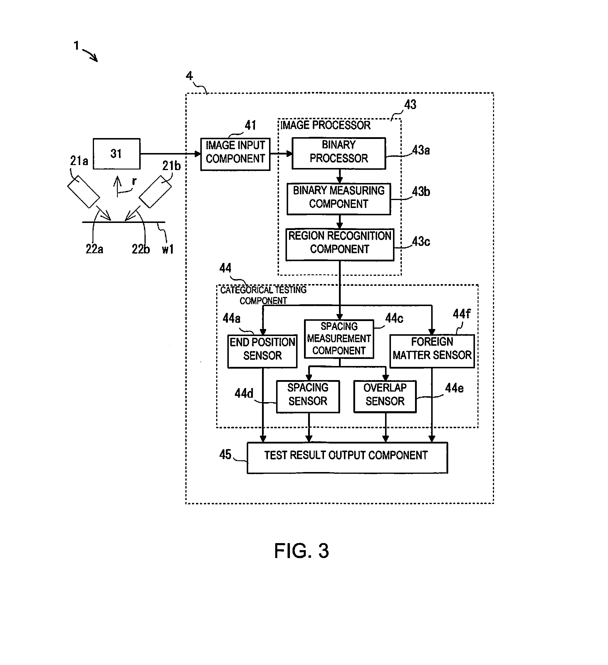
[0059]A test device 1 comprises an illumination component 2, an observat...


PUM


Abstract

A device for testing an application state of a plurality of strips of fiber reinforced plastic tape affixed in rows on a surface of a structure, the device includes an illumination component emits observation-use illuminating light beams toward a test region of the fiber reinforced plastic tape, an observation component observes reflected light from the test region, and a testing component tests the application state of the fiber reinforced plastic tape based on an image observed by the observation component. The illumination component includes a plurality of irradiation units that light simultaneously and are disposed such that a pair of the observation-use illuminating light beams are emitted from directions that are mutually symmetrical with respect to a normal line of the test region, and an illumination direction change component that changes the directions of the pair of observation-use illuminating light beams emitted from the illumination component about the normal line.

Description

CROSS-REFERENCE TO RELATED APPLICATIONS[0001]This application is a U.S. National stage of International Application No. PCT / JP2013 / 064575 filed on May 27, 2013. This application claims priority to Japanese Patent Application No. 2012-174494 filed with Japan Patent Office on Aug. 7, 2012. The entire disclosure of Japanese Patent Application No. 2012-174494 is hereby incorporated herein by reference.BACKGROUND[0002]1. Field of the Invention[0003]The present invention relates to a device for testing the application state of a plurality of strips of fiber reinforced plastic tape affixed in rows on the surface of a structure.[0004]2. Background Information[0005]Fiber reinforced plastic sheets have been used in recent years in sports applications and in aerospace applications that require a lightweight and high-performance structure. Many sheet-like molding intermediate materials in a semi-cured state in which carbon fiber has been impregnated with a thermoplastic resin, which is called p...

Claims


Application Information

Patent Timeline
IPC IPC(8): G01N21/86G01N21/892G06T7/00G01N21/88
CPCG01N21/86G01N21/8851G01N21/8806G01N2201/02G06T7/0004G01N2201/061G01N21/892G01N21/952G01N21/8422G01N2021/8472
Inventor SASAMOTO, HIROMICHIKOBAYASHI, HISASHINOGAMI, YOSHIO
Owner TORAY ENG CO LTD
Features
  • R&D
  • Intellectual Property
  • Life Sciences
  • Materials
  • Tech Scout
  • Unparalleled Data Quality
  • Higher Quality Content
  • 60% Fewer Hallucinations
Learn More