Sensor unit

Active Publication Date: 2015-08-06
AISIN SEIKI KK
View PDF18 Cites 3 Cited by
  • Summary
  • Abstract
  • Description
  • Claims
  • Application Information

AI Technical Summary

Benefits of technology

[0018]With the above arrangement, the molten resin charged from the charging position fills the area forming the sensing surface and then flows toward a space area forming the base part, and further into a space area forming the connecting part from the space area form

Problems solved by technology

In such a case, not only a short shot may hinder the resin from flowing with a sufficient amount for forming the sensing surface, but also the resi

Method used


Image

  • Sensor unit
  • Sensor unit
  • Sensor unit

Examples


Embodiment Construction

[0032]Embodiments of the present invention will be described hereinafter in reference to the accompanying drawings.

[Sensor Unit]

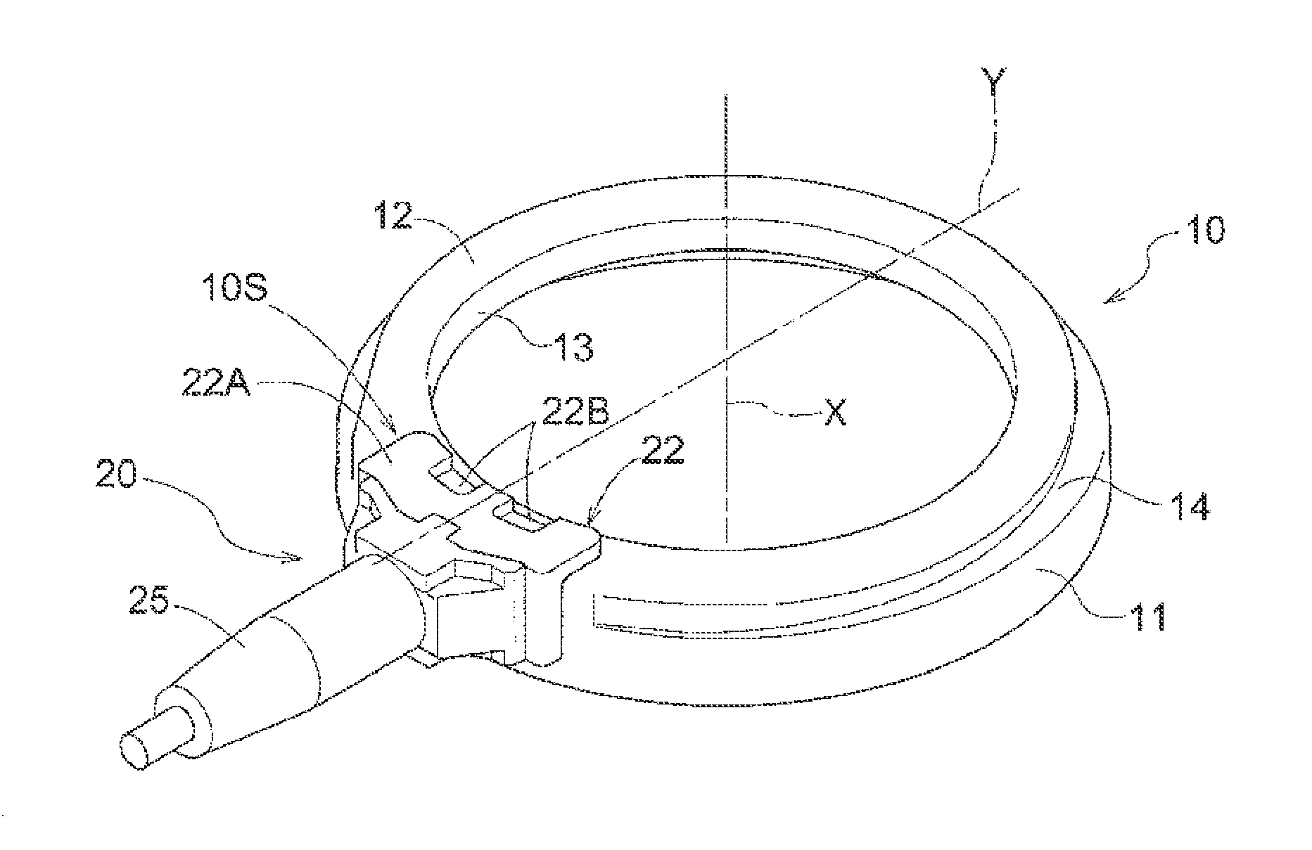
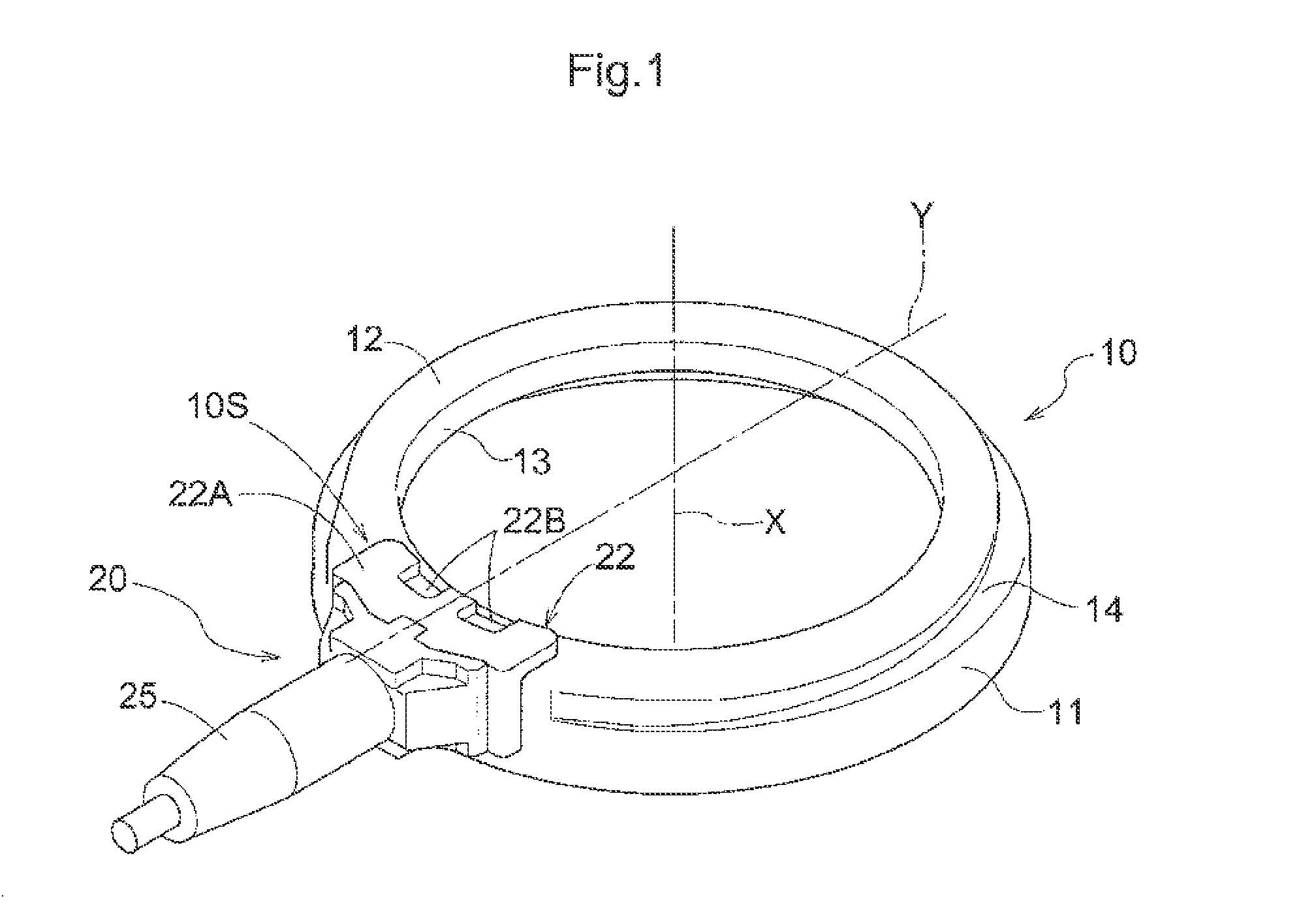
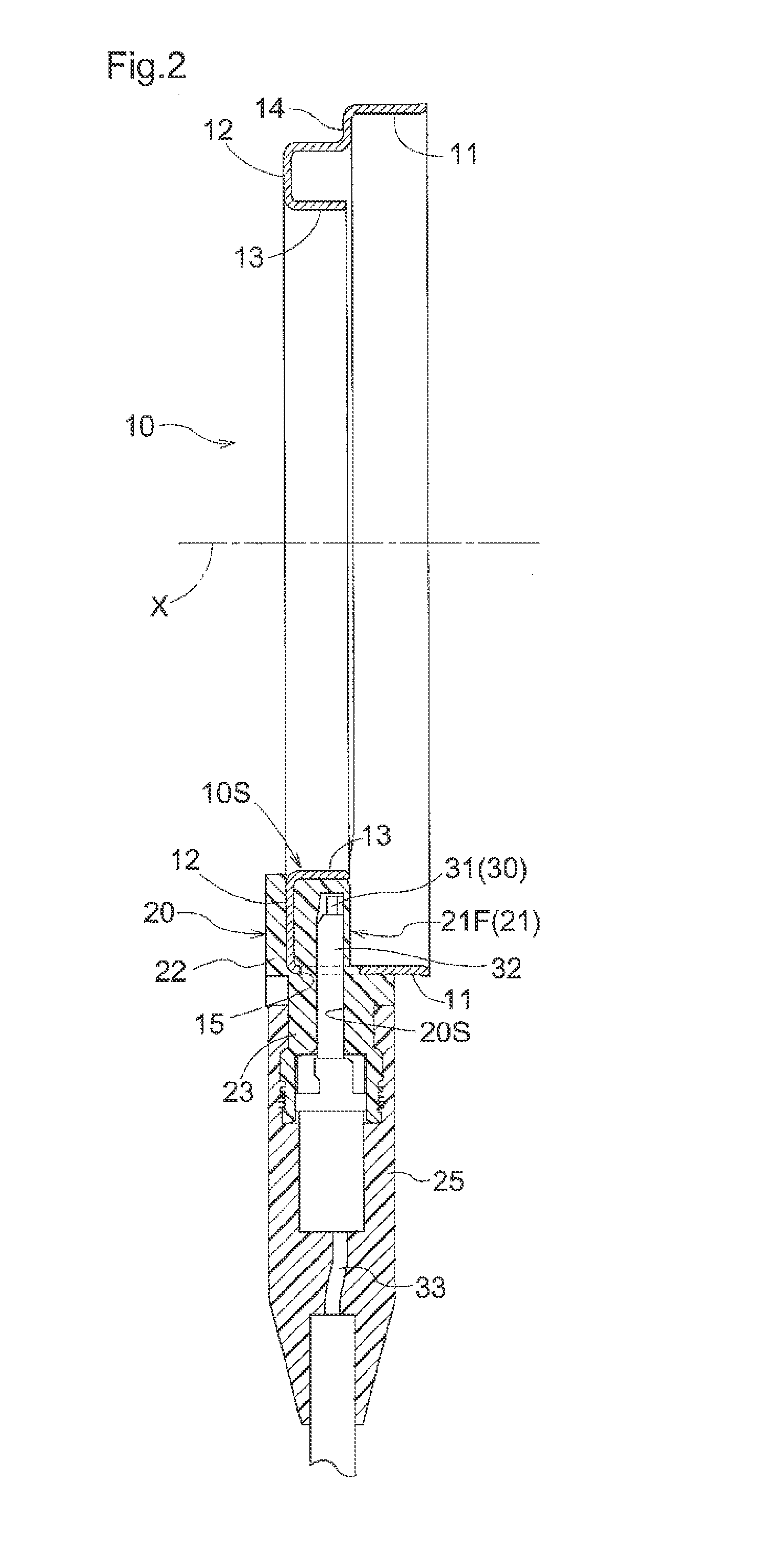
[0033]Referring to FIGS. 1 and 2, a sensor unit includes an annular fixing member 10 centering around an axis X, a casing 20 formed integrally with the fixing member 10 by resin molding, and a sensor 30 housed in a sensor receiving part 20S of the casing 20.

[0034]The sensor unit is used to detect rotation of a rotary shaft such as a vehicle axel, and has a magnet-sensitive element acting as the sensor 30, including a Hall element, a magnetoresistive effect element or the like, configured to detect magnetism of a (permanent) magnet rotatable in unison with the axle (not shown).

[0035]Referring to FIGS. 1 to 10, the fixing member 10 has a cylindrical outer wall 11 formed in a tubular shape centering around the axis X, an end wall 12 extending from one end of the cylindrical outer wall 11 to be perpendicular to the axis X, and a cylindrical inner wall 13 formed...


PUM

PropertyMeasurementUnit
Thicknessaaaaaaaaaa
Widthaaaaaaaaaa

Abstract

A sensor unit with a sensing surface molded properly on an outer surface of a sensor receiving part is provided. The sensor unit includes a resin casing formed with an annular fixing member, and a sensor receiving part formed in the casing for receiving a sensor housed. A sensing surface that faces a target object is formed within the sensor receiving part. A resin charging position in molding the casing is set to a position deviated circumferentially from a central position in a width of the sensing surface. In particular, resin is charged into the fixing member from a gate arranged on an extending line of a first through-bore formed in a position corresponding to the charging position.

Description

TECHNICAL FILED[0001]The present invention relates to an improved sensor unit.BACKGROUND ART[0002]Patent Literature 1 discloses an example of a sensor unit including an annular fixing element (“ring part” in Patent Literature 1), and a sensor element fixed to the fixing element by resin molding. According to the construction disclosed in Patent Literature 1, the sensor element is configured to sense magnetism of a target rotary object rotatable in unison with a rotary shaft, thereby to detect rotating speed of the rotary object.CITATION LISTPatent Literature[0003]Patent Literature 1: Japanese Unexamined Patent Application Publication No. 2009-264941SUMMARY OF INVENTION[0004]With a sensor including a sensor element for sensing magnetism of a magnet disposed in a rotary element thereby to detect rotation of the rotary element, the sensibility is enhanced due to a short distance between the magnet and the sensor element, thereby to achieve error-reduced detection.[0005]Further, with a ...

Claims


Application Information

Patent Timeline
IPC IPC(8): B29C45/14G01R33/00
CPCG01D5/245B29C45/14311B29C45/14344B29C45/2708B29C2045/14327G01R33/0047G01P3/487G01D11/245B29C45/14065B29L2031/752G01P1/026B29C45/14336B29C2045/0027
Inventor KAWASAKI, KOJIADACHI, KAZUHIROOKAMURA, KYOICHI
Owner AISIN SEIKI KK
Why Eureka
Try Eureka