High-voltage harness connection structure for electrically driven vehicle

a technology of high-voltage harness and connection structure, which is applied in the direction of electric devices, battery packs, cell components, etc., can solve the problems of limiting the layout freedom of battery packs in vehicles, power units, and sometimes damaged harnesses, so as to prevent damage and enhance vehicle layout freedom of battery packs

Active Publication Date: 2015-08-06
NISSAN MOTOR CO LTD
View PDF3 Cites 25 Cited by
  • Summary
  • Abstract
  • Description
  • Claims
  • Application Information

AI Technical Summary

Benefits of technology

[0013]Thus, by configuring the interference of the power unit with the high-voltage harness in response to the retraction of the power unit in a form of a contact interference by inclination, at the time of front-crush generation, even if the power unit retracts in the vehicle rearward direction upon an impact force, the high-voltage harness would be prevented from being damaged.
[0014]As a result, as compared with the case where the high-voltage harness is routed in a vehicle longitudinal direction, it is possible to arrange the power unit and the battery pack more closely spaced to each other in the vehicle longitudinal direction so that the vehicle layout freedom of the battery pack is enhanced.

Problems solved by technology

During the progress of the retraction, the harness is subject to bending exceeding the bending limit of the high-voltage harness, the harness sometimes will be damaged.
Consequently, when placing the power unit and the battery pack in the longitudinal direction of the vehicle, it is necessary to secure the vehicle longitudinal direction spacing between the power unit and the battery pack sufficiently in consideration of the amount of retraction of the power unit at the time of the front-crush., which in turn will pose restriction on the layout freedom of the battery pack in a vehicle.
Therefore, even if the power unit comes to interfere with the high-voltage harness, the power unit would be subjected to a contact interference with the high-voltage harness that is arranged inclined, at the battery-side high-voltage connector terminal, in the vehicle width outside direction with respect to the vehicle longitudinal direction.

Method used


Image

  • High-voltage harness connection structure for electrically driven vehicle
  • High-voltage harness connection structure for electrically driven vehicle
  • High-voltage harness connection structure for electrically driven vehicle

Examples


Embodiment Construction

[0024]Hereinafter, Embodiments of the present invention will be described with reference to the drawings. In embodiments of the invention, numerous specific details are set forth in order to provide a more thorough understanding of the invention. However, it will be apparent to one of ordinary skill in the art that the invention may be practiced without these specific details. In other instances, well-known features have not been described in detail to avoid obscuring the invention.

[0025]First, a description will be given of the configuration.

[0026]The configurations of the high-voltage harness connection structure for an electric vehicle in one or more embodiments of the present invention will be separately described in “SCHEMATIC CONFIGURATION OF ELECTRIC VEHICLE EQUIPPED WITH HARNESS CONNECTION STRUCTURE ”, “DETAILED CONFIGURATION OF BATTERY PACK BP”, and “HIGH-VOLTAGE HARNESS CONNECTION STRUCTURE”, respectively.

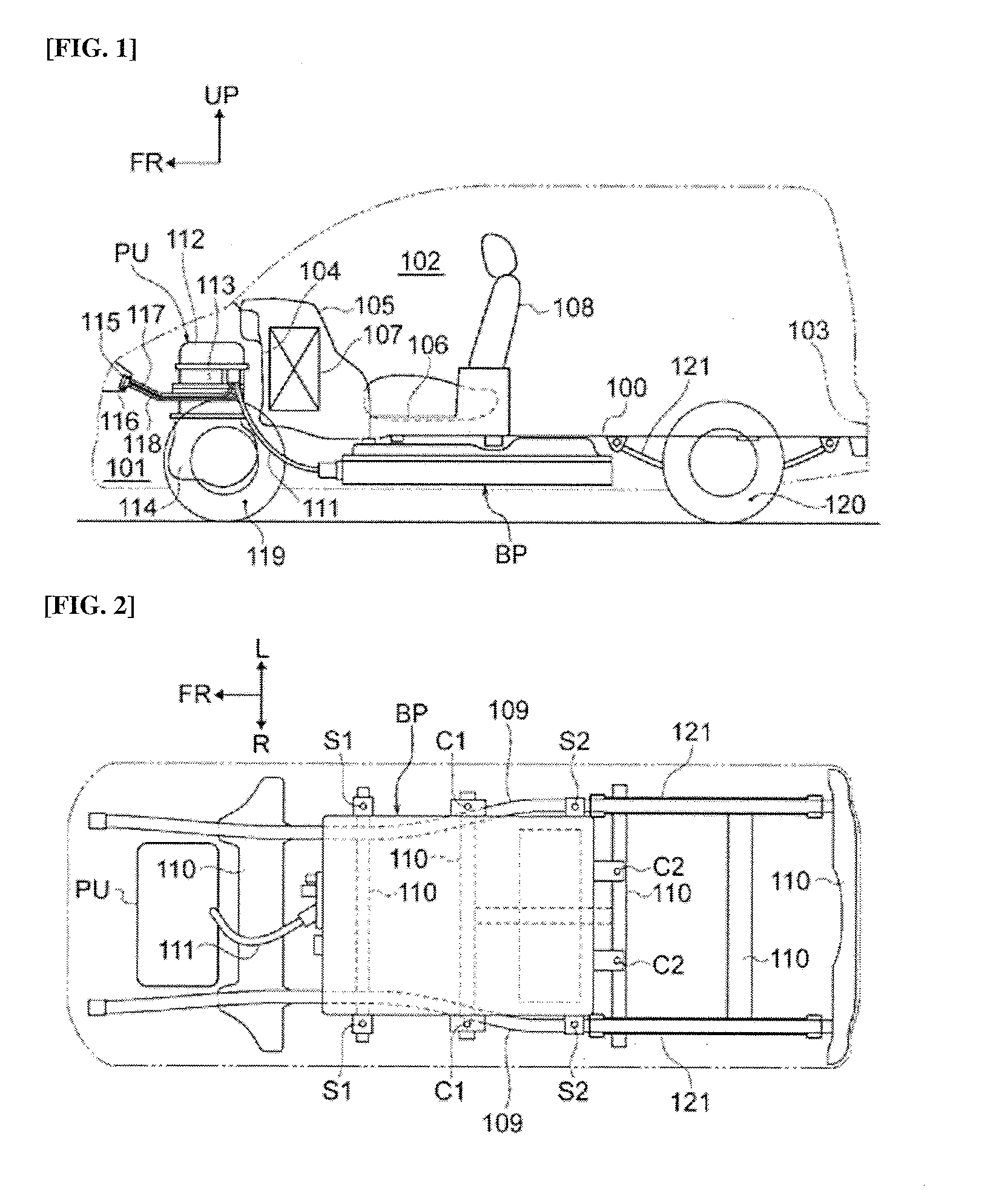
[0027][Schematic Configuration of Electric Vehicle Equipped with Har...


PUM

PropertyMeasurementUnit
voltageaaaaaaaaaa
angleaaaaaaaaaa
widthaaaaaaaaaa

Abstract

A high-voltage harness connection structure for an electrically driven vehicle, having a battery pack disposed in an underfloor position of the vehicle and having a battery-side high-voltage connector terminal disposed on a front end thereof, a power unit arranged in a vehicle forward position with respect to the battery pack and having a unit-side high-voltage connector terminal disposed thereon, and a high-voltage harness that connects the battery-side high-voltage connector terminal and the unit-side high-voltage connector terminal. The harness connection surface of the battery-side high-voltage connector terminal forms a harness connection inclined surface so that the high-voltage harness is connected to be inclined outwardly in a vehicle width direction with respect to a vehicle longitudinal direction, and routed in an outwardly bent state in the vehicle width direction with respect to the vehicle longitudinal direction.

Description

CROSS-REFERENCE TO RELEVANT APPLICATIONS[0001]The present application claims priority from Japanese Patent Application No. 2012-186036 filed in the Japan Patent Office on Aug. 27, 2012, the disclosure of which is herein incorporated by reference in its entirety.BACKGROUND[0002]1. Technical Field[0003]The present invention relates to a high-voltage harness connection structure for an electrically driven vehicle, which connects a battery pack and a power unit via a high voltage harness.[0004]2. Related Art[0005]Conventionally, as a harness connection structure of the electrically driven vehicle, a structure is known in which a battery-side high-voltage electric connector terminal provided at the front end of a battery pack and a unit-side high-voltage connector terminal provided on a power unit are connected by a high-voltage harness arranged in the longitudinal direction of the vehicle (for example, Patent Document 1).[0006]Patent Document 1: JP 2011-20622 ASUMMARY[0007]However, in t...

Claims


Application Information

Patent Timeline
Patent Type & Authority Applications(United States)
IPC IPC(8): B60R16/02B60K1/04B60K1/00H01M50/262
CPCY02T10/7005Y02T10/705B60Y2304/01B60K1/04B60L3/0007H01M2220/20B60K1/00B60K2001/0438B60R16/0215B60L11/18H01M2/1072B60L11/1877H01M50/262B60L50/66Y02T10/70Y02E60/10
Inventor TANIGAKI, TATSUNORITSUJIMURA, NORIHISAHATTA, KENTARO
Owner NISSAN MOTOR CO LTD
Why Eureka
Try Eureka