
Variable positioner

Active Publication Date: 2015-08-06
RAYTHEON TECH CORP
View PDF5 Cites 5 Cited by
  • Summary
  • Abstract
  • Description
  • Claims
  • Application Information

AI Technical Summary

Benefits of technology

The patent describes a gas turbine engine with a variable positioner that maintains the position of a rotating component relative to a static hardware component. The positioner includes an anti-rotation slot that interfaces with an anti-rotation feature on the rotor to prevent rotation of the positioner. The positioner also has an interface shoulder that interfaces with an interface surface of the rotating component to keep it in position axially. The technical effects of this invention include improved stability and efficiency of the gas turbine engine, as well as reduced wear and tear on the components.

Problems solved by technology

In some examples, gas turbine engine size and weight constraints reduce the possible size of the radially protruding shoulder.
In such a case, the shoulder / spacer arrangement described above can be insufficient to maintain the rotor position relative to the static hardware forward and aft of the rotor.

Method used


Image

  • Variable positioner
  • Variable positioner
  • Variable positioner

Examples


Embodiment Construction

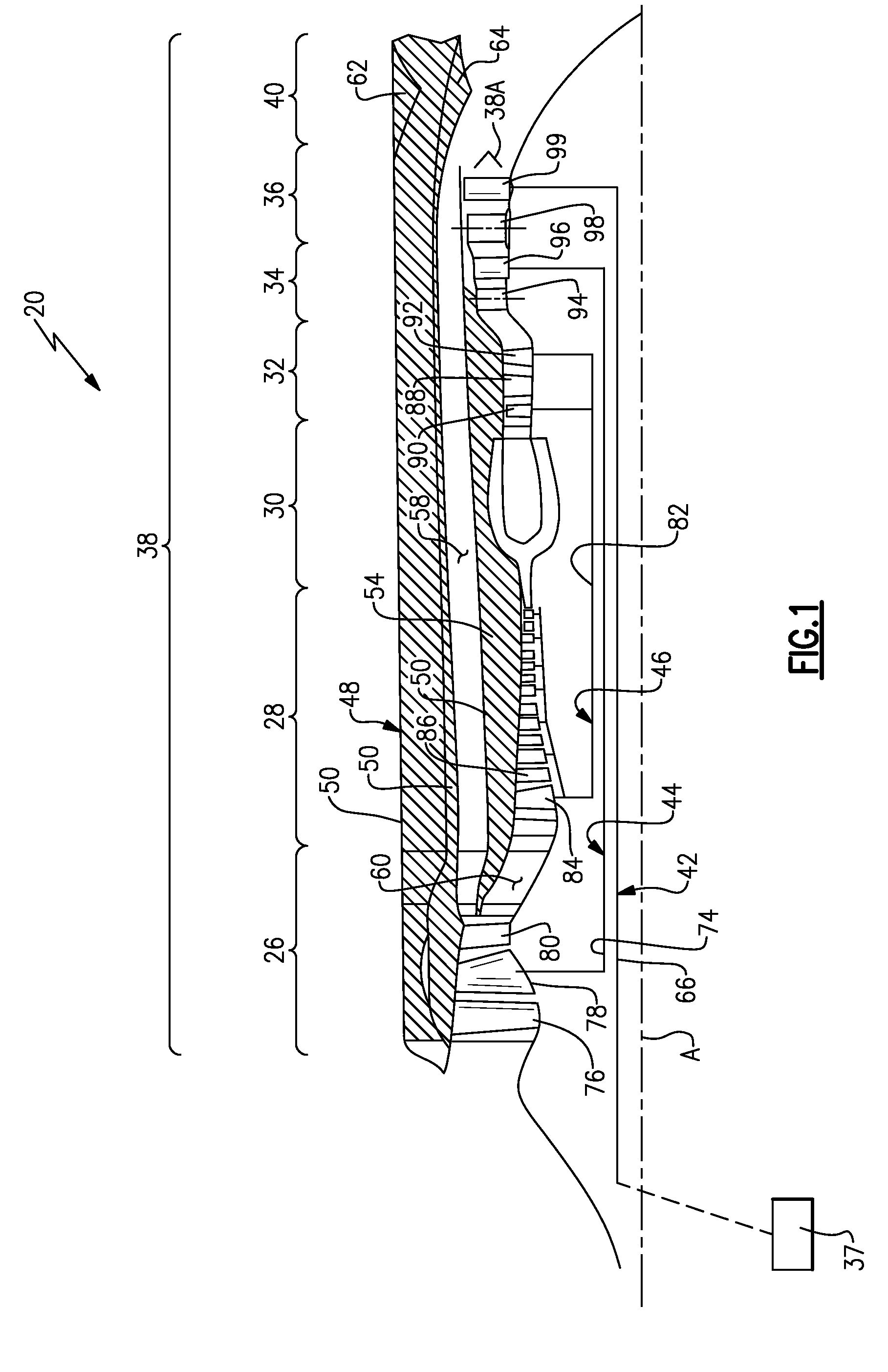
[0032]FIG. 1 schematically illustrates a gas turbine engine 20. The gas turbine engine 20 is disclosed herein as a variable cycle three-spool turbine that generally includes a low pressure compressor fan section 26, a high pressure compressor section 28, a combustor section 30, a high pressure turbine section 32, an low pressure turbine section 34, a power turbine section 36, a bypass duct section 38 and a nozzle section 40. The power turbine section 36 drives a helicopter rotor 37. Additional sections may include an augmentor section 38A among other systems or features such as a geared architecture which may be located in various other engine sections than that shown such as, for example, aft of the low pressure turbine section 34. The sections are defined along a central longitudinal engine axis A.

[0033]The engine 20 generally includes a power turbine spool 42, a low pressure turbine spool 44 and a high pressure turbine spool 46 which rotate about the engine central longitudinal a...


PUM

PropertyMeasurementUnit
Diameteraaaaaaaaaa
Heightaaaaaaaaaa
Torqueaaaaaaaaaa

Abstract

A variable positioner includes a body portion with a cylindrical component, and an axially aligned through hole in the body position. A threading protrudes radially inward from an inner surface of the axially aligned through hole. A first axial end of the variable positioner defines an interface surface for interfacing with a rotor arm.

Description

CROSS-REFERENCE TO RELATED APPLICATION[0001]This application claims priority to U.S. Provisional Application No. 61 / 934871 filed on Feb. 3, 2014.STATEMENT REGARDING GOVERNMENT SUPPORT[0002]This invention was made with government support under Contract No. W911W6-08-2-0001 awarded by the United States Army. The Government has certain rights in this invention.TECHNICAL FIELD[0003]The present disclosure relates generally to a variable positioner for positioning a rotor relative to a shaft.BACKGROUND[0004]Gas turbine engines, such as those used on commercial and military aircraft, utilize multiple shafts to drive multiple compressor sections. Each of the shafts is connected to, and driven by, a turbine section. By way of example, some gas turbine engines include a high pressure turbine section that is connected to, and drives, a high pressure compressor section via a shaft and a low pressure turbine section that is connected to, and drives, a low pressure compressor section, a helicopte...

Claims


Application Information

Patent Timeline
IPC IPC(8): F01D25/16F02C3/107
CPCF01D25/16F02C3/107F02C7/36F01D5/025F01D5/026F05D2240/52Y02T50/60Y10T29/49238
Inventor JUH, CHRISTOPHER M.WASSERMAN, DAVID J.
Owner RAYTHEON TECH CORP
Learn More