
Pumping Unit and Counterbalance System for Pumping Units

a technology of pumping unit and counterbalance system, which is applied in the direction of positive displacement liquid engine, gearing, borehole/well accessories, etc., can solve the problems of reducing the stroke length of the pumping unit, reducing the pumping capacity, and becoming relatively unbalanced at the larger angle of walking beam tilt, so as to reduce the overall work of pumping and reduce the overall work. , the effect of efficient offset of vertical translation

Active Publication Date: 2015-08-06
GUIDEMASTER MFG
View PDF0 Cites 2 Cited by
  • Summary
  • Abstract
  • Description
  • Claims
  • Application Information

AI Technical Summary

Benefits of technology

[0007]The current invention includes a counterbalance system to counterbalance the downhole weight connected to a reciprocating pumping unit to more efficiently offset the vertical translations of the downhole weights with each stroke of the reciprocating pump unit. This substantially eliminates a significant portion of ineffective work associated with previous pumping units, thus reducing the overall work of pumping, energy consumption, and, consequently, lift costs.
[0010]As will be discussed further below in connection with the drawings, a counterbalance system according to this embodiment allows the downhole weight on the walking beam to be counterbalanced without requiring horizontal movement of the counterweights. Reducing or eliminating horizontal movement of the counterweights reduces the load on the pumping unit motor and thus reduces the power consumed by the pumping unit motor to reduce lift cost.
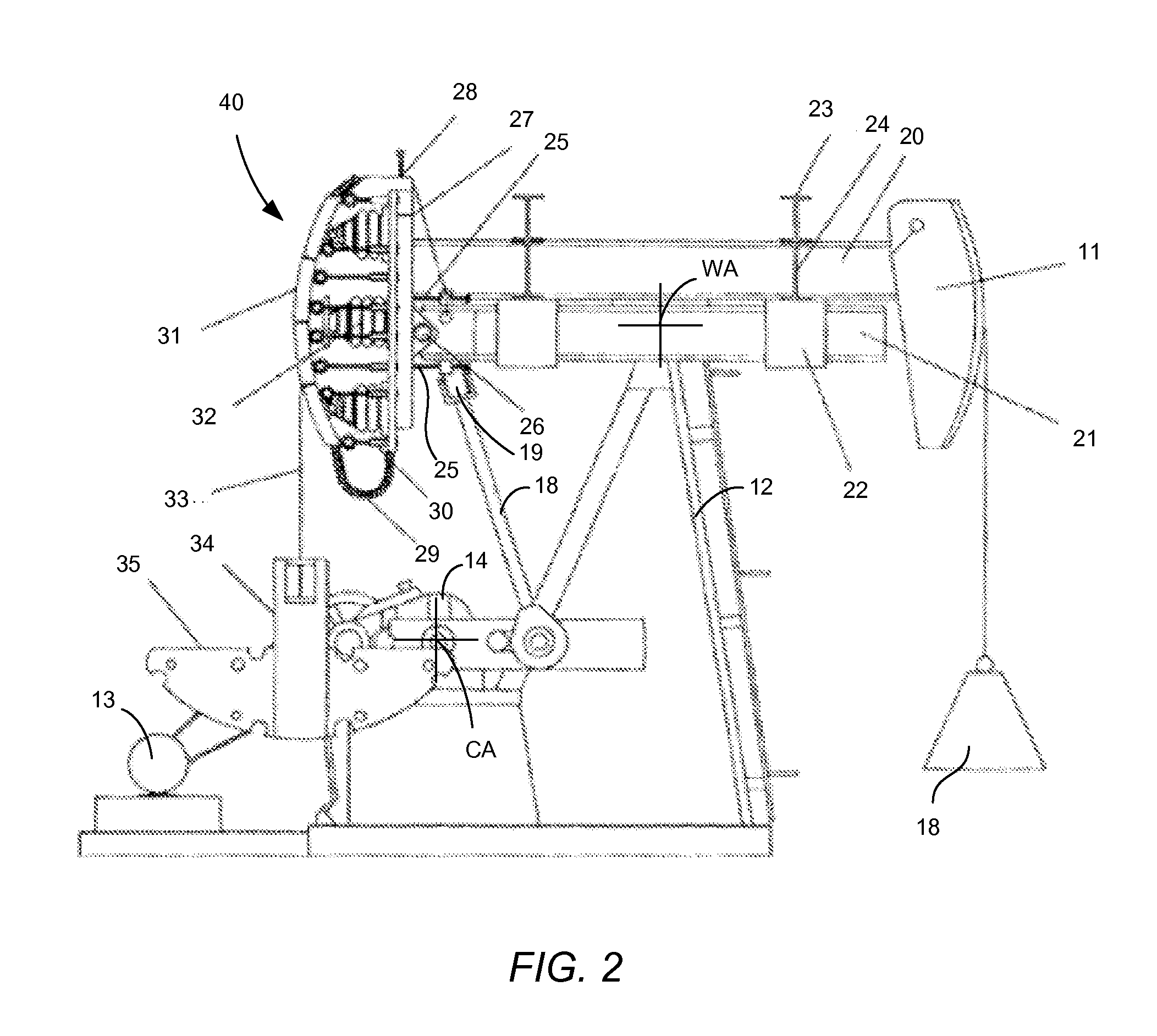
[0011]In another aspect of the invention a first outrigger complex which includes the first outrigger member and a second outrigger complex which includes the second outrigger member may be mounted together with the outrigger support structure to improve the efficiency of the pumping unit. In particular, the first outrigger complex, the second outrigger complex, and the outrigger support structure may be mounted on the walking beam so that the first and second outrigger beams are positioned below the level of the walking beam and axially along the walking beam so as to place the center of gravity of a combined walking beam complex, outrigger support structure, first outrigger complex, and second outrigger complex at a pivot axis for the walking beam of the pumping unit.
[0013]The placement of the center of gravity of the combined walking beam complex, outrigger support structure, first outrigger complex, and second outrigger complex at or near the pivot axis for the walking beam reduces induced torques in the pumping unit arising from the misalignment of the center of gravity of the walking beam and the pivot axis of the walking beam which is present in many pumping units. This reduction in induced torques reduces the power requirements of the pumping unit and thus reduces lift costs.
[0014]Embodiments of a counterbalance system in accordance with the present invention do not preclude the use of frequency driving to summarily improve efficiency. Furthermore, embodiments of a counterbalance system within the scope of the invention do not require significant changes in a pre-existing pumping unit. Removal of the crankshaft counterweights (which can be used on the present counterbalance system counterweights) with rebalancing of the pumping unit with the present counterbalance system in place are all that is required to effect the gain in efficiency. In scaled prototype studies the gain in efficiency was well over fifty percent (50%). In addition to lift cost savings through reduced energy consumption, unloading the crankshaft loads can reduce maintenance costs and increase component longevity and reduce component failure.

Problems solved by technology

These “beam-balanced” pumping units suffer from reduced stroke length and reduced pump capacity.
Also, they become relatively unbalanced at larger angles of walking beam tilt.
Therefore, they have been limited to use in relatively shallow wells.
Reducing this to horizontal and vertical vectors only, fifty percent (50%) of the work used to move the counterweights is horizontal, and thus ineffective.
Thus fifty percent (50%) of the power drive unit work expended in a crank-balanced pumping unit can be ineffective in pump output.
However, because the vertical and horizontal components cannot be completely isolated, the reduction of ineffective power consumption is limited.
Even with prior art counterweight arrangements, driving the pumping unit requires considerable energy input from the motor, which is commonly an electric motor.
Because the upward stroke of the pumping unit and downhole reciprocating pump produce a relatively low volume of pumped fluids, between 5-40 liters per stroke, long run-times for these pumps can consume relatively large amounts of energy.

Method used


Image

  • Pumping Unit and Counterbalance System for Pumping Units
  • Pumping Unit and Counterbalance System for Pumping Units
  • Pumping Unit and Counterbalance System for Pumping Units

Examples


Embodiment Construction

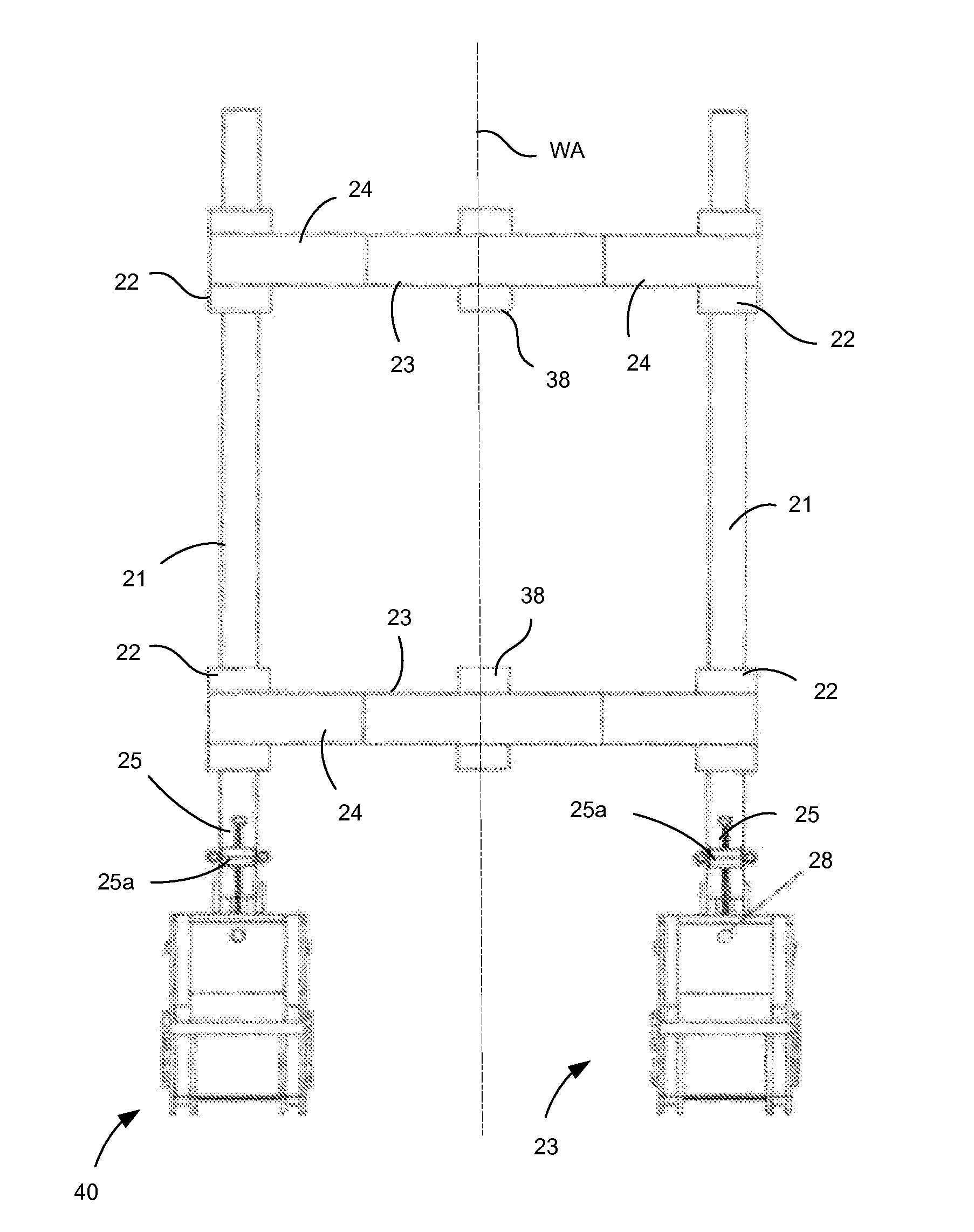
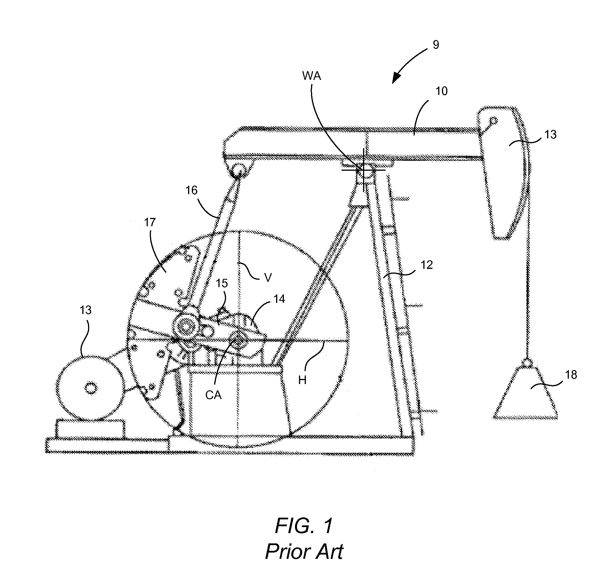
[0025]In the following description FIG. 1 will be used to describe a prior art pumping unit and to illustrate aspects of the prior art pumping unit which lead to certain operational inefficiencies. FIGS. 2 and 3 will then be used to describe a counterbalance system according to certain embodiments of the present invention as mounted in an operating position on the prior art pumping unit of FIG. 1. FIGS. 4-8 show the example counterbalance system separate from a pumping unit.

[0026]Referring to FIG. 1, a pumping unit 9 includes a walking beam 10 pivotally mounted on a walking beam support 12 (also referred to as a “Samson post”). In this arrangement, walking beam 10 may pivot about a walking beam axis WA extending perpendicular to the plane of the drawing. A horse head 11 is connected at a front end of walking beam 10. Pumping unit 9 also includes a motor 13 (also may also be referred to as a “prime mover”) which is operably connected via a drive belt to a reducing gear arrangement 14...


PUM


Abstract

A counterbalance system may include an outrigger support structure, a first elongated outrigger member, and a second elongated outrigger member. The outrigger support structure is adapted to be mounted in an operating position on a walking beam of a pumping unit. The first elongated outrigger member is connected to the outrigger support structure at a first lateral side of the counterbalance system. The second outrigger member is also connected to the outrigger support structure, but is connected at a second lateral side of the counterbalance system. A first suspension element may be connected to the first outrigger member and a second suspension element may be connected to the second outrigger member. Suitable counterbalance weights may be connected to the first suspension element while additional counterbalance weights may be connected to the second suspension element. These counterbalance weights connected to the first and second suspension elements may be used to counterbalance the weight on the downhole weight on the walking beam.

Description

CROSS-REFERENCE TO RELATED APPLICATIONS[0001]This is a continuation of U.S. patent application Ser. No. 13 / 097,754 filed Apr. 29, 2011, and entitled “Cross-Jack Counterbalance System,” which claimed the benefit of U.S. Provisional Patent Application 61 / 332,766 filed May 8, 2010 of the same title. The Applicant claims the benefit of U.S. patent application Ser. No. 13 / 097,754 under 35 U.S.C. §120, and claims the benefit of U.S. Provisional Patent Application No. 61 / 332,766 under 35 U.S.C. §119(e). The entire content of each of these prior patent applications is incorporated herein by this reference.TECHNICAL FIELD OF THE INVENTION[0002]The present invention relates pumping units such as those used for artificial lift in oil wells. More particularly, the invention relates to counterbalance systems for use with pumping units as well as to pumping units which incorporate the counterbalance systems.BACKGROUND OF THE INVENTION[0003]In the field of oil and gas production, a reciprocating b...

Claims


Application Information

Patent Timeline
Patent Type & Authority Applications(United States)
IPC IPC(8): F04B47/14E21B43/12
CPCF04B47/14Y10T74/2156E21B43/127Y10T74/18182
Inventor SMITH, ALAN D.
Owner GUIDEMASTER MFG
Learn More