Heat exchanger utilizing tubular structures having internal flow altering members and external chamber assemblies

a technology of heat exchangers and tubular structures, which is applied in the direction of tubular elements, lighting and heating apparatus, cleaning heat exchange devices, etc., can solve the problems of reducing pressure resistance, reducing the efficiency of pipe heat exchangers, and prone to damage of thinner tubes, so as to reduce overall cost, reduce the overall cost, and reduce the overall length of enhanced tubes for heat exchange applications

Inactive Publication Date: 2015-08-06
MIKUTAY CORP
View PDF6 Cites 0 Cited by
  • Summary
  • Abstract
  • Description
  • Claims
  • Application Information

AI Technical Summary

Benefits of technology

[0021]In an embodiment of the present invention, the cylindrical tubular member and the chamber assemblies for a heat exchanger are provided, for example, for a condenser, evaporator, radiator, etc. The heat exchanger may also be a heater core, intercooler, or an oil cooler for an automotive application (e.g., steering, transmission, engine, etc.) as well as for non-automotive applications. An advantage of the present invention is that the heat exchanger has a larger surface area for radiating heat over a shorter distance than that of a conventional heat exchanger, with the surface area provided by both the cylindrical tubular member and the chamber assemblies. With the provision of a large surface area for exchanging heat, the efficiency of the heat exchanger is greatly increased. Additionally, the structural rigidity provided by having the cylindrical tubular member comprised of a single seamless or seamed tube lends itself for use in high internal or external pressure applications.
[0022]Another advantage of the present invention is that the overall length of the enhanced tube for heat exchanging applications may be shortened compared to a conventional heat exchanger, which in turn provides for a lower overall cost, as less raw material and less packaging are necessary. Additionally, the cylindrical tubular member may be made from a thicker gage material, allowing the heat exchanger to be used for high pressure applications. Furthermore, the smaller footprint of the present invention lends itself to be used in applications where space is limited. Yet another advantage of the present invention over a conventional heat exchanger is that the manufacturing process may be simpler because the present invention requires less fragile components and less manufacturing steps. The present invention provides an easy to assemble heat exchanger, providing enhanced heat exchanging performance while being cost effective. The present invention also excels in high pressure applications typical of commercial and industrial applications, by providing a rigid cylindrical tubular member, which can be manufactured of thick gage tubular material. The entire unit may be brazed together, or any portion of the unit can be brazed first, and then additional components may be brazed, soldered together, or attached by mechanical means, with or without utilization of gaskets.
[0023]The present invention also lends itself for ease of assembly by having a single piece cylindrical tubular member. The cylindrical tubular member may be a single piece tubular structure with a plurality of inlet orifices and outlet orifices formed at predetermined intervals in the wall of the cylindrical tubular member. The orifices can be machine drilled, punched out by pressing, or formed by other mechanical means, as long as the method used creates orifices that go through the entire thickness of the wall of the cylindrical tubular member. A plurality of flow altering members may be inserted inside the cylindrical tubular member to align with an inlet orifice and an outlet orifice pairing. In an embodiment of the present invention, a plurality of flow altering members may be formed from a single piece of material, or a plurality of flow altering members may be coupled together to form a single piece of material with a plurality of flow altering features. In another embodiment of the present invention, a plurality of flow altering members may be inserted inside the cylindrical tubular member, with the length of each flow altering member predetermined, so that once the individual flow altering members are inserted into the cylindrical tubular member end-to-end, each flow altering member aligns to a pairing of an inlet orifice and an outlet orifice. On the outer surface of the cylindrical tubular member, a plurality of chamber assemblies are coupled, each chamber assembly being positioned over a pair comprising of an inlet orifice and an outlet orifice.
[0024]Chamber assemblies may be mechanically coupled to the outer surface of the cylindrical tubular member, or may be attached by other means, such as brazing, soldering, or welding, for example. A plurality of chamber assemblies may be first combined together to form a unitary unit of a plurality of chamber assemblies, prior to coupling the chamber assemblies to the cylindrical tubular members. By combining a plurality of chamber assemblies prior to coupling to the cylindrical tubular members, the assembly process is simplified. Additionally, a plurality of chamber assemblies may be formed from a single piece of material, by stamping, casting, hydroforming, or other machining processes.
[0025]In another embodiment of the present invention, fins or plate members may be attached to the outside surface of the cylindrical tubular member, to the outer surface of chamber assemblies or to surfaces of both the cylindrical tubular member and the chamber assemblies. Fins or plate members attached to the outer surface further increase the surface area of a heat exchanger, thereby enhancing the performance characteristics of the heat exchanger. Fins and plate members provide an economical means to increase the heat exchanging capability of a heat exchanger by enhancing the surface area available for heat transfer, without greatly increasing the size of a heat exchanger or costing more to produce a heat exchanger.
[0026]In yet another embodiment of the present invention, the chamber assembly size may vary from one chamber assembly to the next.

Problems solved by technology

The efficiency of pipe heat exchangers is limited by the amount of surface area available for the transfer of heat.
However, the pressure resistance is reduced, and the thinner tubes are more prone to damage.
Also, the assembly process is complicated due to the fragile nature of the parts.
In addition, extruded tubes are prone to plugging during the manufacturing process, particularly if a brazing process is utilized.
The complexity of the extruding process results in higher costs and higher defect rates.
Furthermore, as flat tubes are generally extruded into shape utilizing metal extrusion processes, only material that can be easily extruded into shape is typically made into flat tubes, restricting the available materials for flat tubes generally to aluminum and various aluminum alloys known in the art.
The overall cost for the flat tube heat exchanging system is higher because a powerful compressor is necessary to move the heat exchanging medium through the smaller openings of the tubes.
The addition of tubes increase the overall cost for the heat exchanging system.
This is detrimental to the performance of a heat exchanger, especially in an application such as an evaporator, wherein pressure drop significantly diminishes the performance of the compressor, for example.
Shell-and-tube heat exchangers typically bundle together generally straight tubes with no surface enhancements either to the inside or the outside of the tubes, resulting in limited heat exchanging performance characteristics.
This causes shell-and-tube heat exchanger to be larger in size to meet a desired heat exchanging performance, thus requiring a large footprint for installation purposes.

Method used


Image

  • Heat exchanger utilizing tubular structures having internal flow altering members and external chamber assemblies
  • Heat exchanger utilizing tubular structures having internal flow altering members and external chamber assemblies
  • Heat exchanger utilizing tubular structures having internal flow altering members and external chamber assemblies

Examples


Embodiment Construction

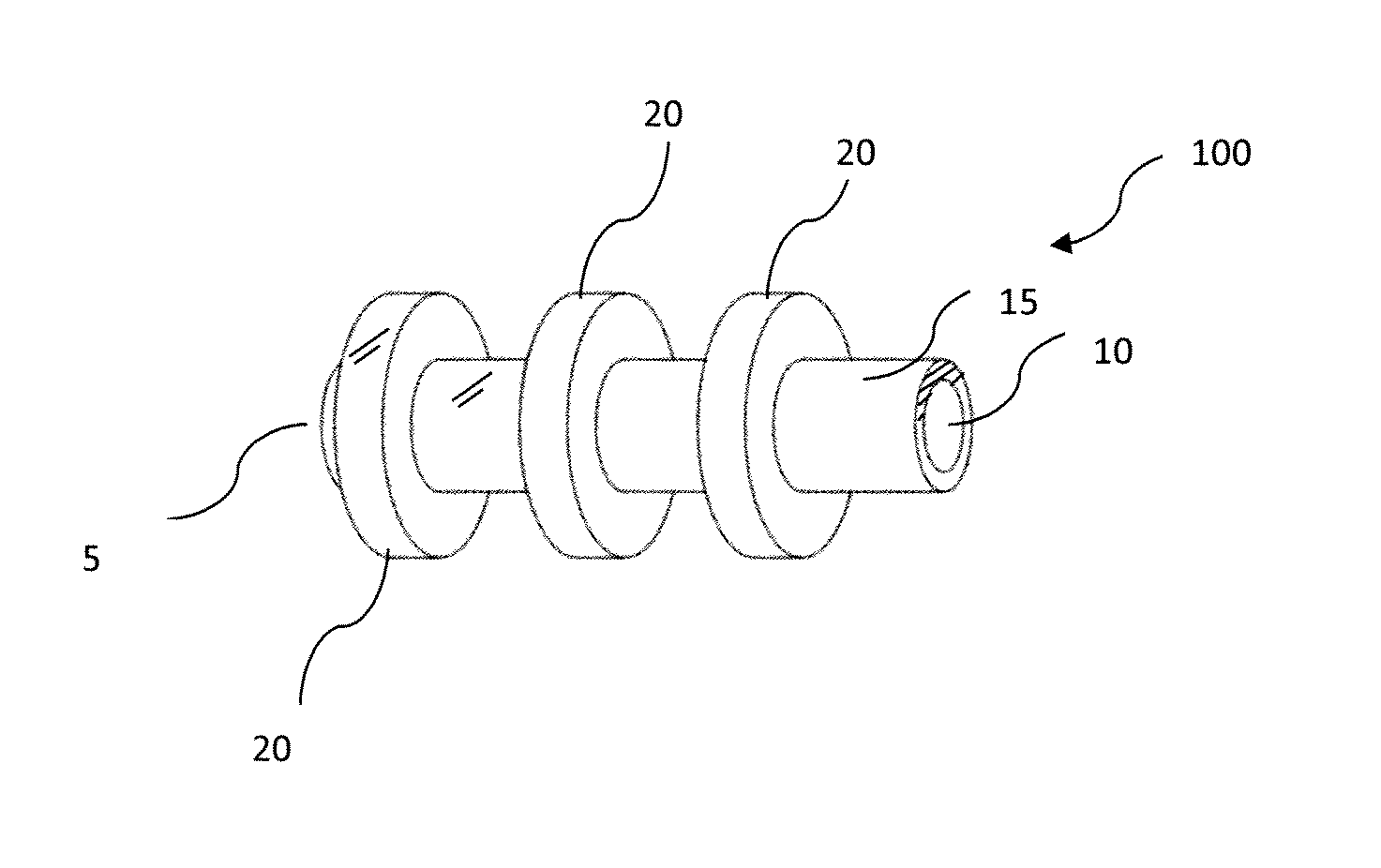
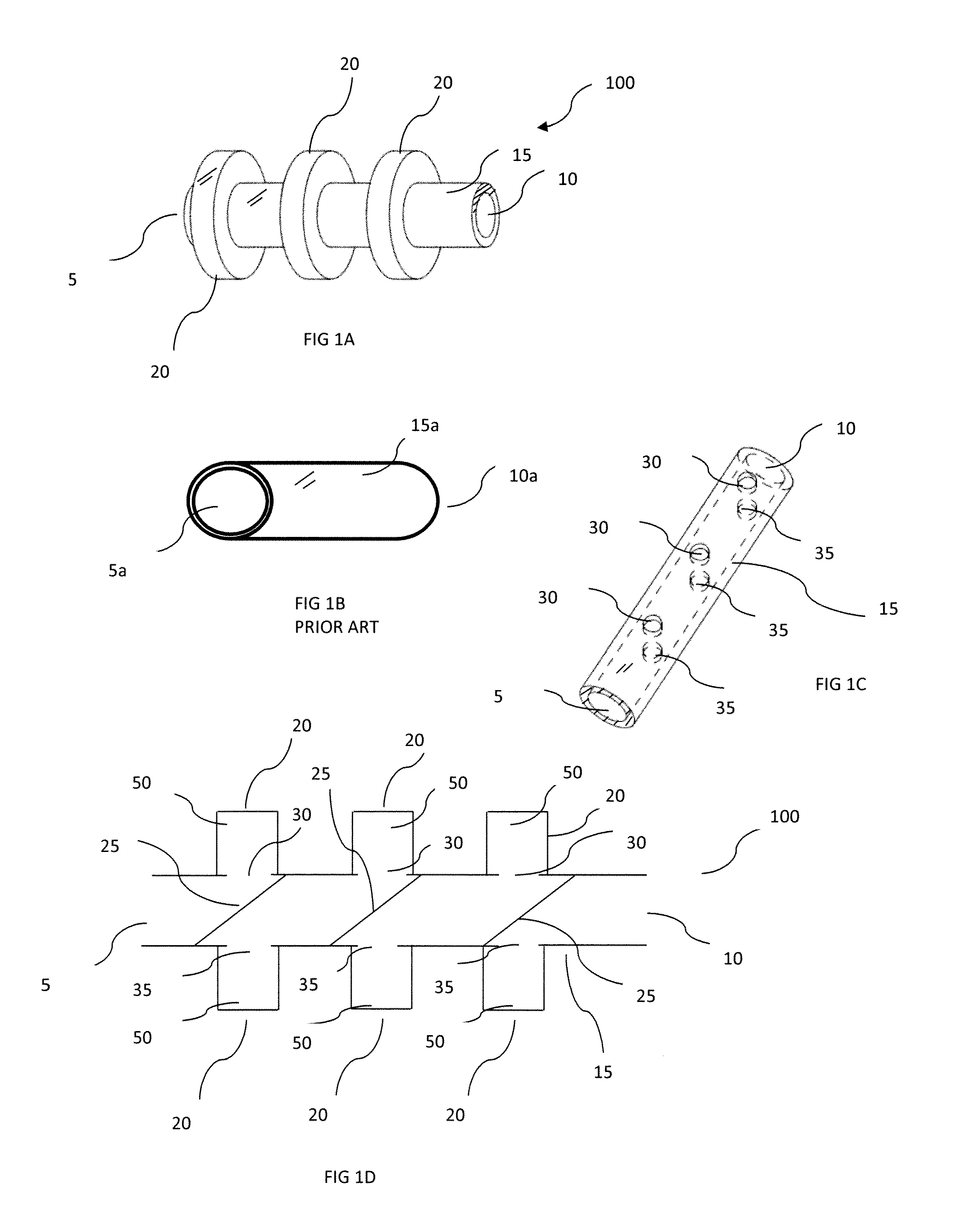
[0071]Referring to the drawings and in particular FIG. 1A, an embodiment of a cylindrical tubular member 100 is shown. The cylindrical tubular member 100 has an inlet 5 to introduce a heat exchange medium into the cylindrical tubular member 100, and an outlet 10 to allow the heat exchange medium to flow out of the cylindrical tubular member 100. The cylindrical tubular member 100 has a tubular structure 15. Referring also to FIG. 1D, the exterior surface of the tubular structure 15 has a plurality of chamber assemblies 20 attached to the exterior surface of the tubular structure 15. Referring to FIG. 1C, the tubular structure 15 features a plurality of inlet orifices 30 and outlet orifices 35, to allow heat exchange medium to flow out of the tubular structure 15, and enter a chamber assembly 20, then allow the heat exchange medium to re-enter the tubular structure 15 from the chamber assembly 20 through the outlet orifice 35. Referring to FIG. 1C and FIG. 1D, the inlet orifice 30 an...


PUM


Abstract

A heat exchanger includes at least one cylindrical tubular member formed from a tubular structure and chamber assemblies. A plurality of flow altering members are coupled at predetermined intervals within the tubular structure. The flow altering members have an angled surface on their respective sides facing the flow of a heat exchange medium. Pairs of inlet orifices and outlet orifices are formed on the wall of the tubular structure at the same intervals as the flow altering members. Chamber assemblies are coupled as a full or partial collar on the exterior of the tubular structure. Each chamber assembly is hollow, permitting fluid flow within, and is in fluid communication with a corresponding inlet orifice, outlet orifice pair so that the heat exchange medium repeatedly flows out of the tubular structure into a chamber assembly and back into the tubular structure. Multiple cylindrical tubular members may be coupled between manifolds.

Description

RELATED APPLICATION DATA[0001]This is a divisional application of U.S. patent application Ser. No. 13 / 677,953, filed Nov. 15, 2012, which is incorporated herein by reference in its entirety.BACKGROUND OF THE INVENTION[0002]1. Field of the Invention[0003]The present invention relates generally to heat exchanger tubes and heat exchangers and, more specifically, to heat exchanger tubes and heat exchangers with a cylindrical tubular member having a plurality of flow altering members within each tubular member. The flow altering members are each paired with a chamber assembly attached to the external surface of the cylindrical tubular member.[0004]2. Discussion of Related Art[0005]Heat exchangers are commonly utilized in systems where it is desired for heat to be removed. Typical basic heat exchangers are made of generally straight pipes, which channel heat exchanging medium within. Headers or manifolds are typically attached to each end of the pipes. These headers and manifolds act as r...

Claims


Application Information

Patent Timeline
Patent Type & Authority Applications(United States)
IPC IPC(8): F28F13/06F28F1/42
CPCF28F1/426F28F13/08F28F1/08F28F13/06F28F13/12F28F1/424F28F1/40F28F9/00F28F9/22F28G13/00
Inventor NITTA, MINORUNITTA, TAKEYOSHI
Owner MIKUTAY CORP
Why Eureka
Try Eureka