
Armor system

a technology of armor system and ceramic material, applied in the field of armor system, can solve the problems of limited repeat hit capability, limited cost, weight, and limited use of ceramic materials in armor, and reduce the ability to protect against subsequent hits, and achieve the effect of superior protection against projectiles and shrapnel and lighter weigh

Active Publication Date: 2015-08-06
EDAN ADMINISTRATION SERVICES IRELAND
View PDF1 Cites 1 Cited by
  • Summary
  • Abstract
  • Description
  • Claims
  • Application Information

AI Technical Summary

Benefits of technology

The present invention is an armor system that offers better protection against firearms and explosive devices while being lightweight and flexible. It can be used on a variety of surfaces and offers customizable configurations.

Problems solved by technology

Although present day armor systems can provide greater protection, there is oftentimes a tradeoff between protection and mobility due to the weight, bulk of armor systems and cost.
However, the use of ceramic materials in armor has been limited by cost, weight and limited repeat hit capability due to the brittleness of the material.
In addition, the use of ceramic material severely limits armor reparability following projectile hit.
Armor-grade ceramics can be extremely hard, brittle materials, and thus following impact of sufficient energy, a monolithic ceramic plate will fracture extensively, leaving many smaller pieces and a reduced ability to protect against subsequent hits.
Thus, multiple hits can be a serious problem with ceramic-based armors.
Although effective, these body armor systems have been criticized for imposing weight and mobility constraints on the user while being expensive to mass-produce.

Method used


Image

  • Armor system
  • Armor system
  • Armor system

Examples


examples

[0095]Reference is now made to the following examples, which together with the above descriptions, illustrate the invention in a non limiting fashion.

Testing of a Ballistic Armor Comprising Asymmetric Cross-Shaped Pellets

[0096]A study was conducted in order to evaluate the ballistics performance of an armor system incorporating the ceramic pellets of the present invention.

Materials and Methods

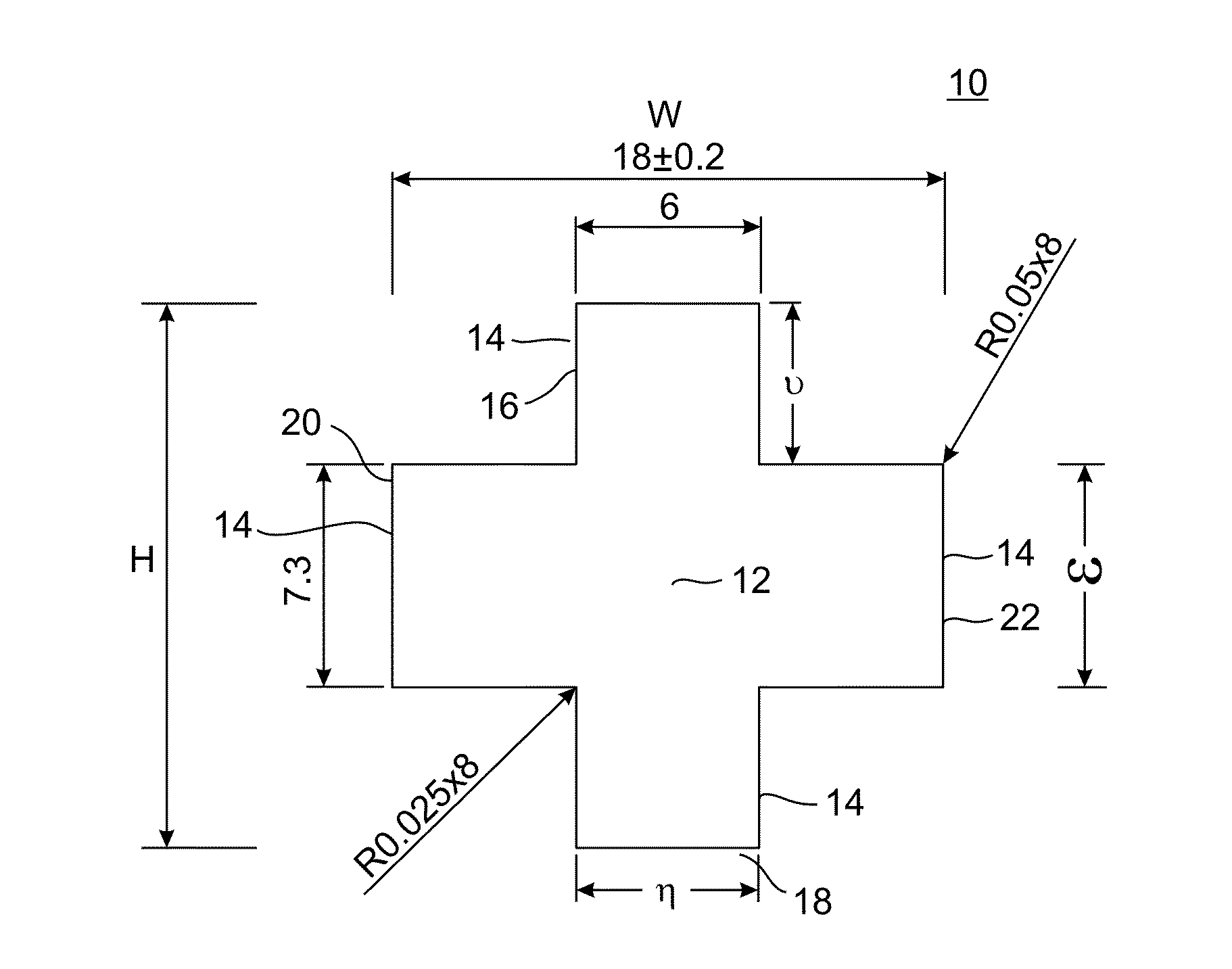
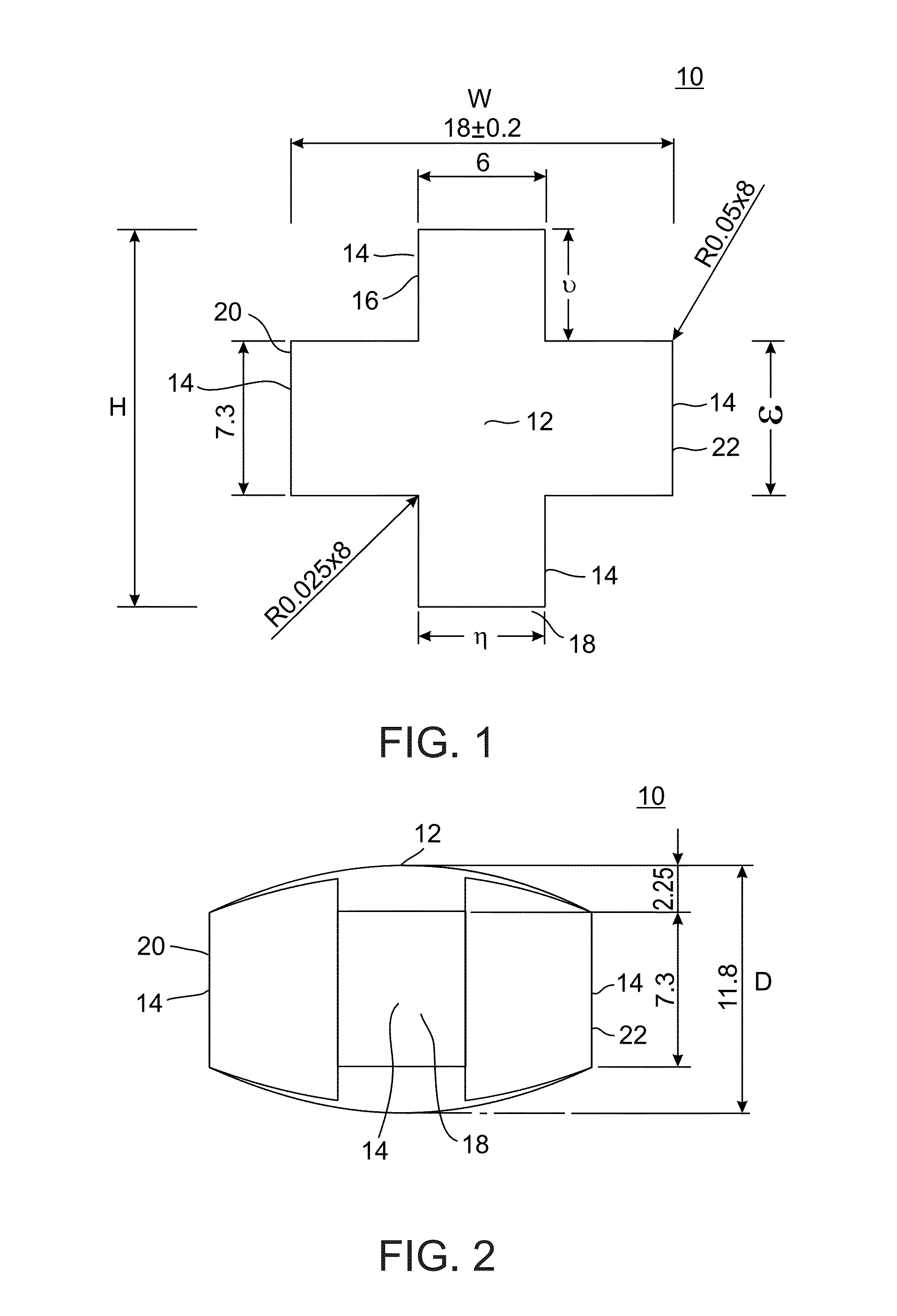
[0097]An armor panel was constructed using a Kevlar outer layer encasing one level of boron carbide pellets arranged in an array of 336 units (dimensions: L-18 mm, W-18 mm, D-11.8 mm) with a back panel of Spectra (10 mm) surrounded by a resin.

[0098]The armor panel weighed at 5.38 Lbs per square foot, 15% less than the ESAPI / XSAPI weight objective (6.2 lbs / square foot).

[0099]The armor panel was tested at threat level D from 100 yards. A first panel was tested with one round, a second for multi-hit capabilities and third and fourth panels were tested at zero yards.

Results

[0100]The results are pre...


PUM

PropertyMeasurementUnit
depthaaaaaaaaaa
heightaaaaaaaaaa
widthaaaaaaaaaa

Abstract

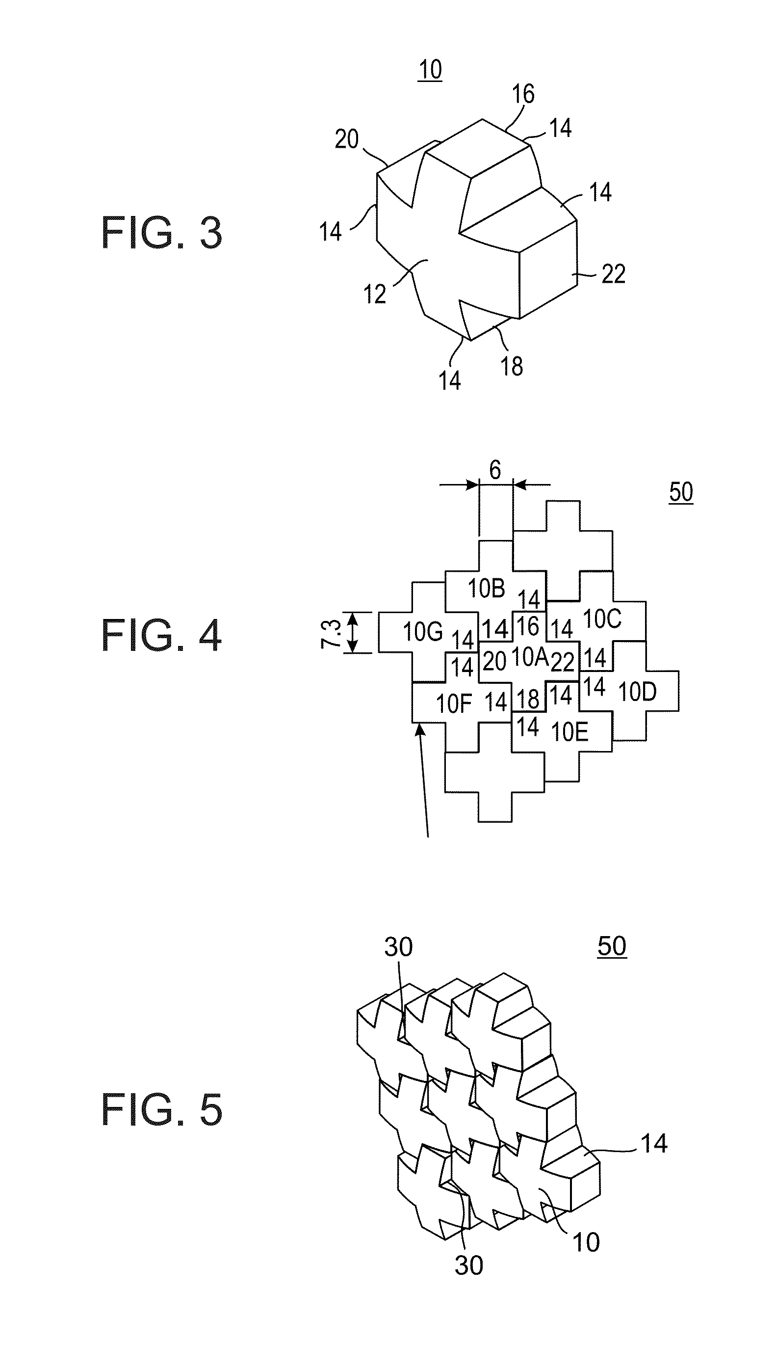
An armor system pellet is provided. The pellet includes a pellet body attached to four projections for interlocking adjacent pellets when arranged in an array. The pellet is configured such that the width of a first pair of co-linear projections is less than a width of a second pair of co-linear projections.

Description

FIELD AND BACKGROUND OF THE INVENTION[0001]The present invention relates to an armor system and, more particularly, to a ballistic armor system that includes an array of interlocked cross-shaped pellets having projections of variable width.[0002]Although present day armor systems can provide greater protection, there is oftentimes a tradeoff between protection and mobility due to the weight, bulk of armor systems and cost. Furthermore, munitions are continually being invented to eliminate the effectiveness of the armor.[0003]The weight and bulk of an armor system tends to be more critical in personal armor (e.g. helmets and body armor). In such cases, advances have led to use of composite materials in order to increase mobility and decrease weight while increasing the degree of protection. For example, military helmets have evolved from the steel helmets of World Wars I and II, to plastic helmets, to the current state-of-the-art composite helmets which include aramid fibers capable ...

Claims


Application Information

Patent Timeline
Patent Type & Authority Applications(United States)
IPC IPC(8): F41H5/04B63B3/10B64D7/00F41H5/24F41H1/02F41H7/02
CPCF41H5/0492B63B3/10B64D7/00F41H7/02F41H5/0421F41H5/0428F41H5/24F41H1/02
Inventor COHEN, HANANYACOHEN, EDWIN
Owner EDAN ADMINISTRATION SERVICES IRELAND
Learn More