
Facility for reducing radioactive material and nuclear power plant having the same

a technology for reducing radioactive materials and nuclear power plants, applied in the field of safety systems, can solve the problems of inability to operate more, low performance in reducing pressure and temperature, and the concentration of radioactive materials in the containment, so as to increase the safety of nuclear power plants and reduce radioactive materials

Active Publication Date: 2015-08-06
KOREA ATOMIC ENERGY RES INST
View PDF13 Cites 19 Cited by
  • Summary
  • Abstract
  • Description
  • Claims
  • Application Information

AI Technical Summary

Benefits of technology

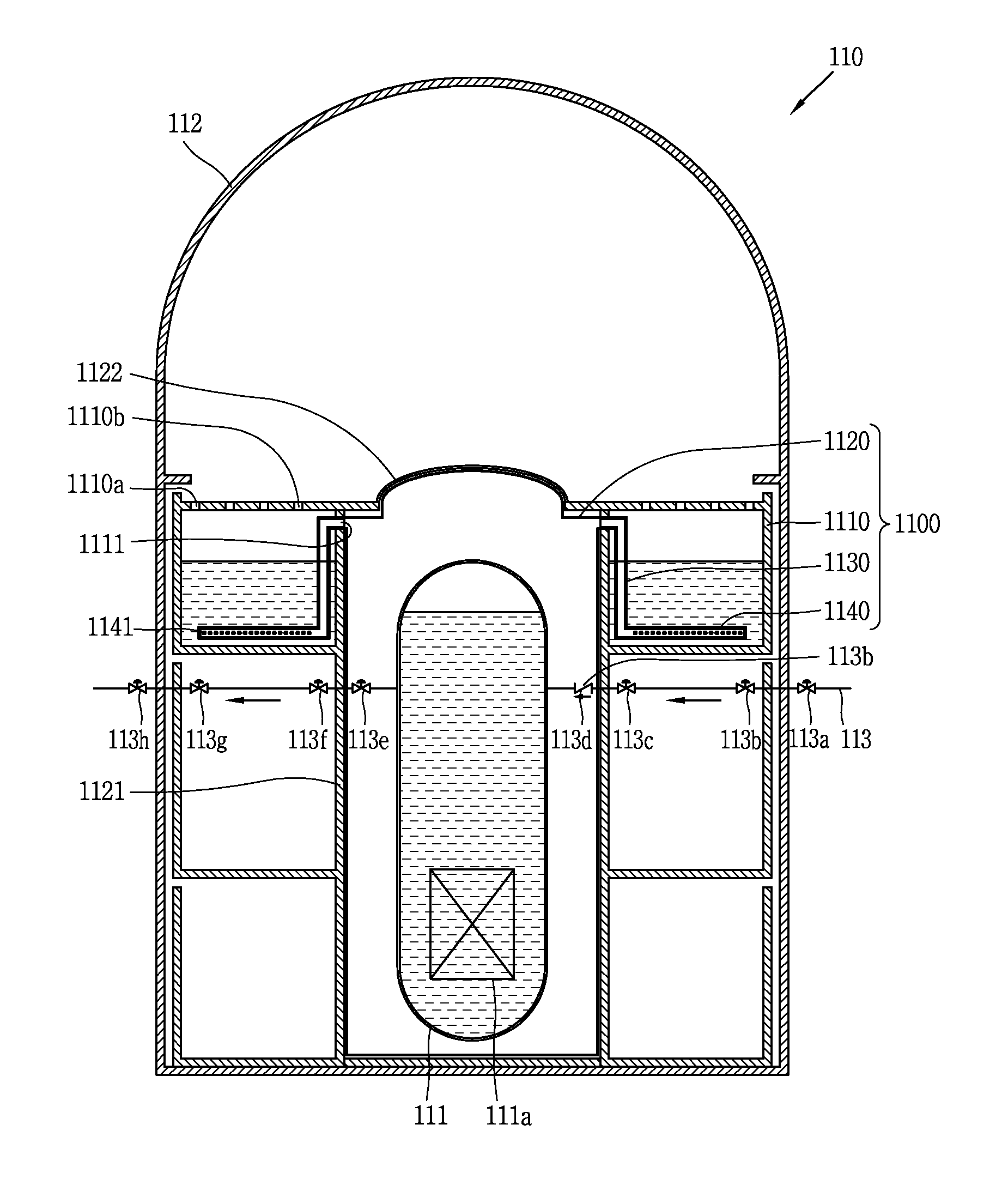
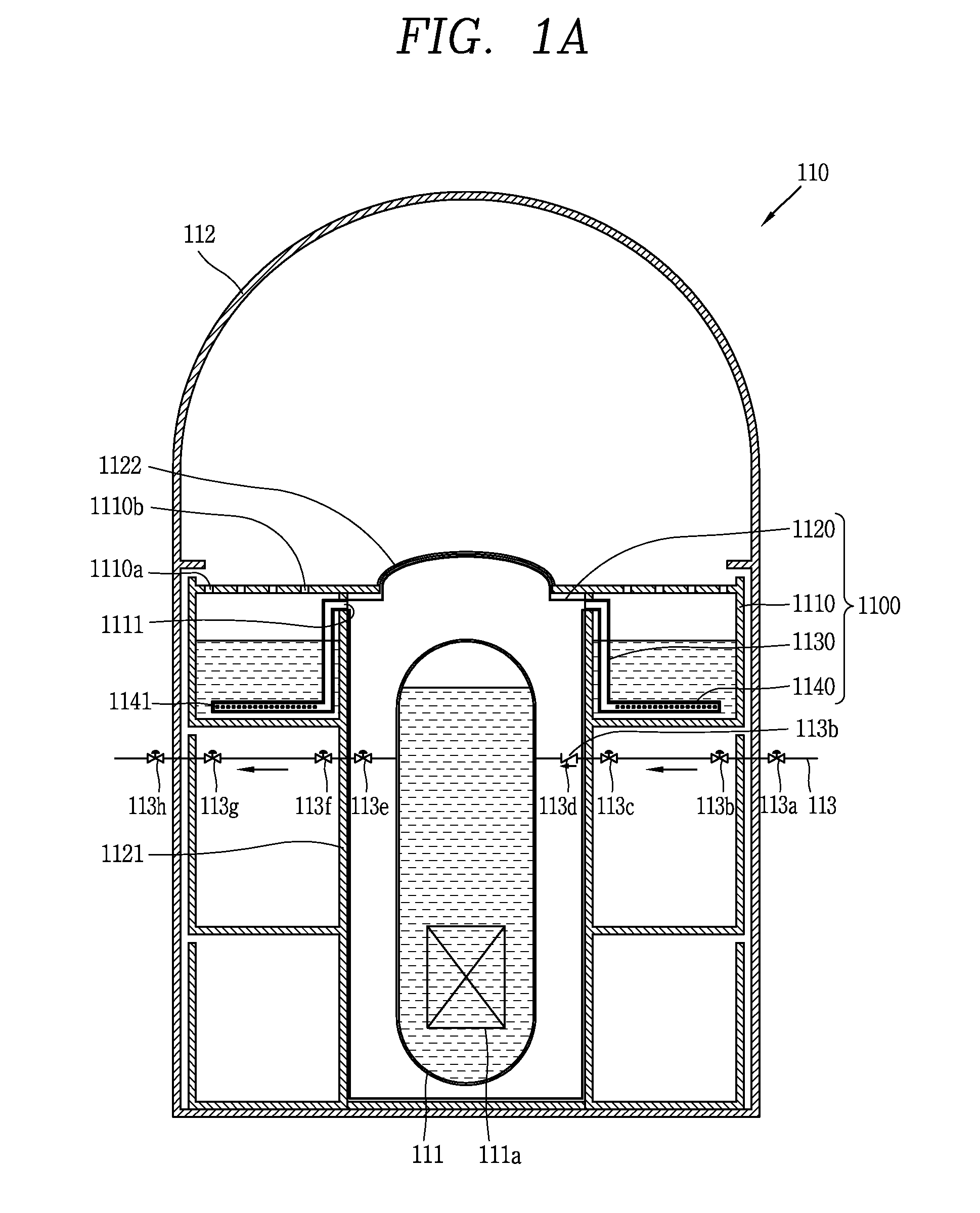
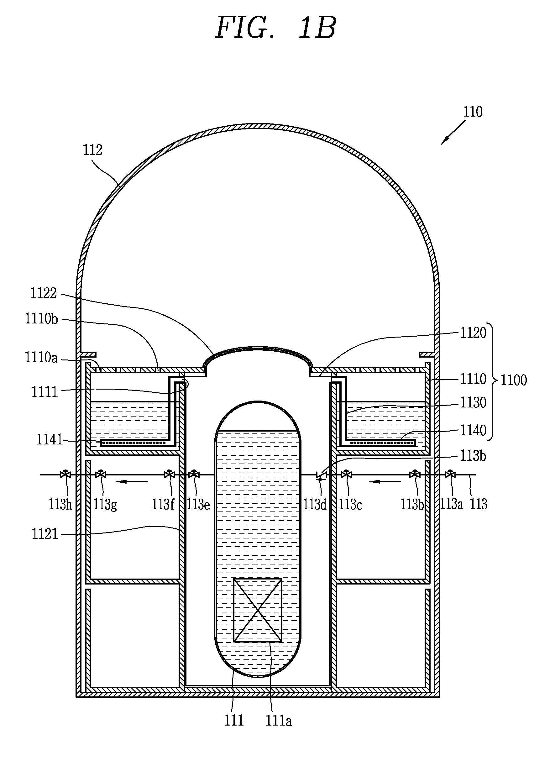
This patent describes a facility to reduce the amount of radioactive material in a nuclear power plant to increase safety. The facility aims to prevent the release of radioactive material during accidents, prevent the need for additional valves, and resolve problems that arise with the use of passive safety systems.

Problems solved by technology

Since the passive containment spray system has a limited storage capacity of cooling water, and thus, cannot be operated more than a predetermined time.
This system uses the natural circulation in the containment similarly to the passive containment cooling system and thus shows a relatively low performance in reducing pressure and temperature and the concentration of radioactive material as compared with the active containment spray system.
However, the active safety system necessarily requires supply of emergency AC power for operating the active components such as pumps when an accident occurs in the nuclear power plant, and without supply of emergency AC power, does not operate.
However, in case the passive safety system is adopted as safety system of the containment, the concentration of radioactive material in the containment would be relatively higher due to a lower performance in containment cooling as compared with the active safety system.
The expansion of EAB may result in a significantly increased cost of constructing the nuclear power plant.

Method used


Image

  • Facility for reducing radioactive material and nuclear power plant having the same
  • Facility for reducing radioactive material and nuclear power plant having the same
  • Facility for reducing radioactive material and nuclear power plant having the same

Examples


Embodiment Construction

[0081]Description will now be given in detail of the exemplary embodiments, with reference to the accompanying drawings. For the sake of brief description with reference to the drawings, the same or equivalent components will be provided with the same reference numbers, and description thereof will not be repeated. In describing the present invention, if a detailed explanation for a related known function or construction is considered to unnecessarily divert the gist of the present disclosure, such explanation has been omitted but would be understood by those skilled in the art. The accompanying drawings are used to help easily understood the technical idea of the present invention and it should be understood that the idea of the present disclosure is not limited by the accompanying drawings.

[0082]It will be understood that although the terms first, second, etc. may be used herein to describe various elements, these elements should not be limited by these terms. These terms are gene...


PUM


Abstract

The present invention provides a facility for reducing radioactive material comprising: a cooling water storage unit installed inside a containment and formed to store cooling water; a boundary unit forming a boundary of radioactive material inside the containment and surrounding a reactor coolant system installed inside the containment to prevent a radioactive material from releasing from the reactor coolant system or a pipe connected with the reactor coolant system to the containment; a connecting pipe connected with an inner space of the boundary unit and the cooling water storage unit to guide a flow of a fluid caused by a pressure difference between the boundary unit and the cooling water storage unit from the boundary unit to the cooling water storage unit; and a sparging unit disposed to be submerged in the cooling water stored in the cooling water storage unit and connected with the connecting pipe to sparge the fluid that has passed through the connecting pipe and the radioactive material contained in the fluid to the cooling water storage unit.

Description

CROSS-REFERENCE TO RELATED APPLICATIONS[0001]Pursuant to 35 U.S.C. §119(a), this application claims the benefit of earlier filing date and right of priority to Korean Application No. 10-2013-0102649, filed on Aug. 28, 2013; Korean Application No. 10-2014-0036321, filed on Mar. 27, 2014; Korean Application No. 10-2014-0083848, filed on Jul. 4, 2014, the contents of which are incorporated by reference herein in their entireties.BACKGROUND OF THE INVENTION[0002]1. Field of the Disclosure[0003]This specification relates to a safety system for securing safety of a nuclear power plant, and in particular, to a facility that may decrease the concentration of a radioactive material in a containment by a passive principle when an accident occurs in the nuclear power plant and a nuclear power plant having the same.[0004]2. Background of the Disclosure[0005]Depending on the position of installation, nuclear reactors are classified into loop-type reactors (e.g., commercial reactors, Korea) with ...

Claims


Application Information

Patent Timeline
IPC IPC(8): G21D3/04G21D1/02G21F1/04
CPCG21D3/04G21D1/02G21F1/04G21C9/00G21C9/004G21C13/02G21C15/18Y02E30/00Y02E30/30
Inventor KIM, YOUNG INKANG, KYUNG JUNKIM, KEUNG KOOHAN, HUN SIKYOON, JU HYEONHA, JAE JOOHWANG, DAE HYUNCHOI, SUHNMOON, JOO HYUNGSHIN, SOO JAI
Owner KOREA ATOMIC ENERGY RES INST
Learn More