Filter device

a filter device and band pass technology, applied in the direction of impedence networks, multiple-port networks, electrical apparatus, etc., can solve the problems of increasing the attenuation at the center of the pass band, limiting the widening of the band, and difficulty in further widening the pass band, so as to achieve the effect of increasing the attenuation

Active Publication Date: 2015-08-06
MURATA MFG CO LTD
View PDF4 Cites 51 Cited by
  • Summary
  • Abstract
  • Description
  • Claims
  • Application Information

AI Technical Summary

Benefits of technology

[0013]Preferred embodiments of the present invention provide a filter device capable of further wideni

Problems solved by technology

It has been, however, difficult to further widen the pass band with the band pass filter using the surface acoustic wave resonator.
However, when a difference in frequency between the attenuation pole at the low-frequency region side and the attenuation pole at the high-frequency region side is made l

Method used


Image

  • Filter device
  • Filter device
  • Filter device

Examples


Embodiment Construction

[0042]Hereinafter, preferred embodiments of the present invention are described with reference to the drawings.

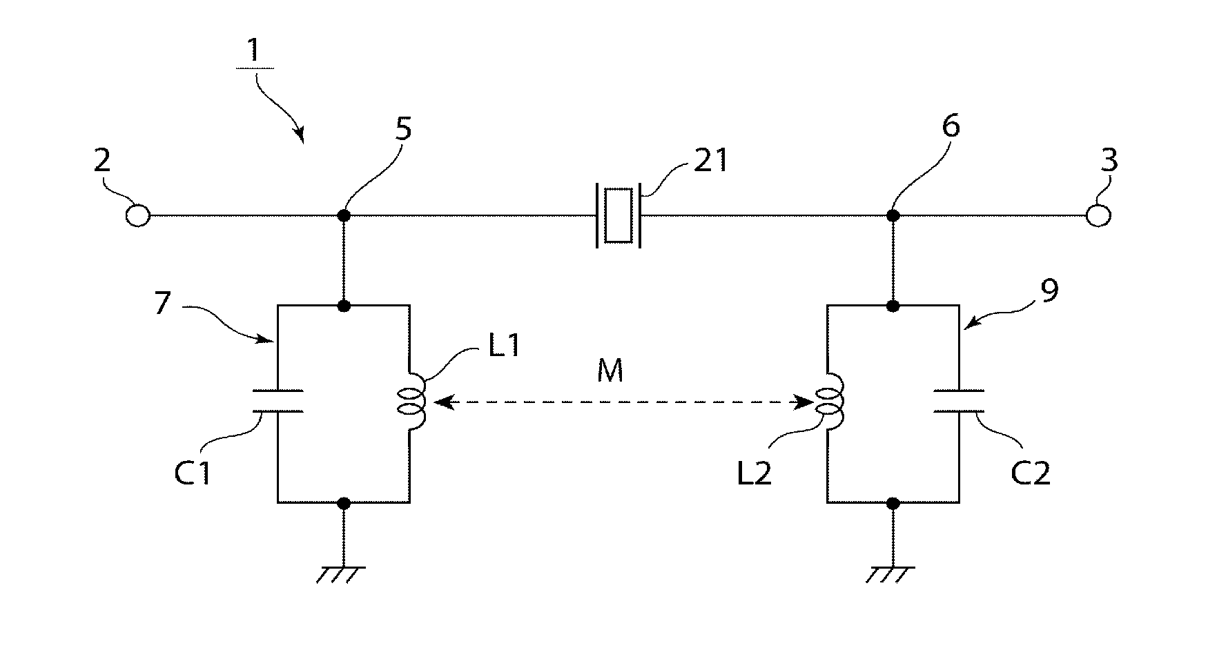
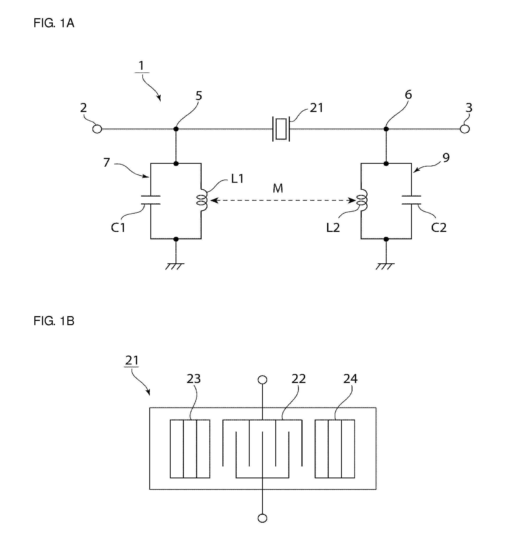
[0043]FIG. 1A is a circuit diagram of a filter device according to a first preferred embodiment of the present invention.

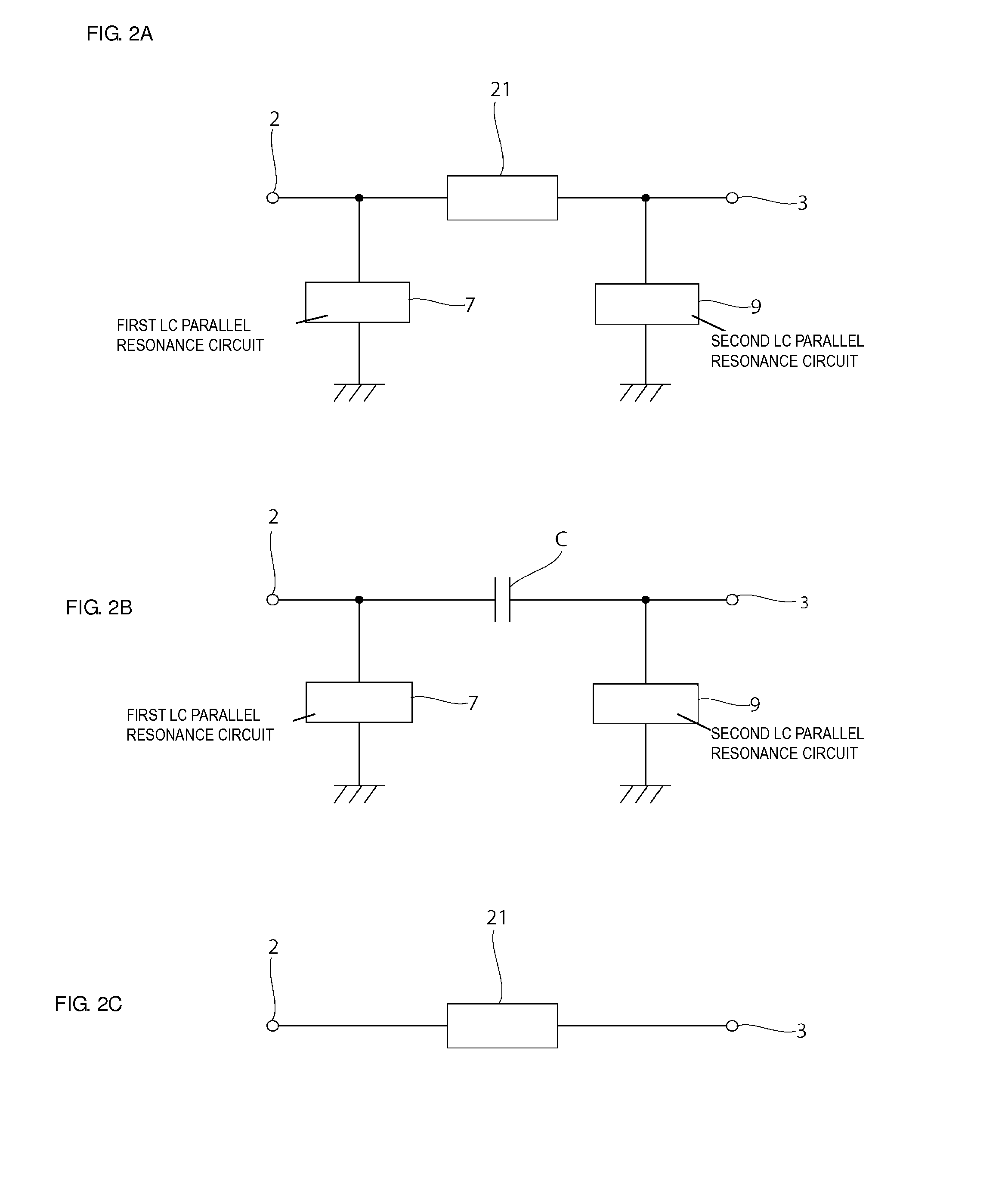
[0044]A filter device 1 includes an input terminal 2 and an output terminal 3. A first LC parallel resonance circuit 7 is connected between a connection point 5 between the input terminal 2 and an elastic wave resonator 21 and a ground potential. The first LC parallel resonance circuit 7 includes an inductance L1 and a capacitor C1 connected in parallel with the inductance L1.

[0045]A second LC parallel resonance circuit 9 is connected between a connection point 6 between the output terminal 3 and the elastic wave resonator 21 and the ground potential. The second LC parallel resonance circuit 9 includes an inductance L2 and a capacitor C2 connected in parallel with the inductance L2.

[0046]The elastic wave resonator 21 is connected between an end portion of...


PUM


Abstract

A filter device includes a first LC parallel resonance circuit having a first inductance and connected between a line connecting an input terminal and an output terminal and a ground potential, a second LC parallel resonance circuit having a second inductance and connected between the line and the ground potential, and at least one elastic wave resonator that is connected between an end portion of the first LC parallel resonance circuit and an end portion of the second LC parallel resonance circuit. Attenuation-frequency characteristics of an LC filter including the first LC parallel resonance circuit, the second LC parallel resonance circuit, and a capacitive property and attenuation-frequency characteristics of the at least one elastic wave resonator are used.

Description

BACKGROUND OF THE INVENTION[0001]1. Field of the Invention[0002]The present invention relates to a band pass filter device, more specifically, relates to a filter device including an LC parallel resonance circuit and an elastic wave resonator.[0003]2. Description of the Related Art[0004]Various existing filter devices have been proposed as band pass filters for mobile communication devices and the like. A pass band of the filter device of this type is required to be wide in many cases.[0005]Japanese Unexamined Patent Application Publication No. 2011-234191 discloses a band pass filter device capable of widening a pass band. In the band pass filter device as disclosed in Japanese Unexamined Patent Application Publication No. 2011-234191, a high pass filter circuit and a low pass filter circuit are connected in series. The high pass filter circuit includes a high pass surface acoustic wave resonator and a high pass inductance element that is connected in parallel with the high pass su...

Claims


Application Information

Patent Timeline
IPC IPC(8): H03H9/54H03H7/01
CPCH03H9/6483H03H7/1775H03H9/542H03H9/64H03H7/09H03H9/6423
Inventor NOSAKA, KOJI
Owner MURATA MFG CO LTD
Why Eureka
Try Eureka