Rapid frame-rate wireless imaging system

a wireless imaging and frame-rate technology, applied in the field of medical imaging, can solve the problems of time-consuming and approximate procedures

Inactive Publication Date: 2015-08-13
CARESTREAM HEALTH INC
View PDF9 Cites 48 Cited by
  • Summary
  • Abstract
  • Description
  • Claims
  • Application Information

AI Technical Summary

Problems solved by technology

This procedure is time-consuming and approximate, sometimes requiring repetition of the adjustment to correct for error.

Method used


Image

  • Rapid frame-rate wireless imaging system
  • Rapid frame-rate wireless imaging system
  • Rapid frame-rate wireless imaging system

Examples


Embodiment Construction

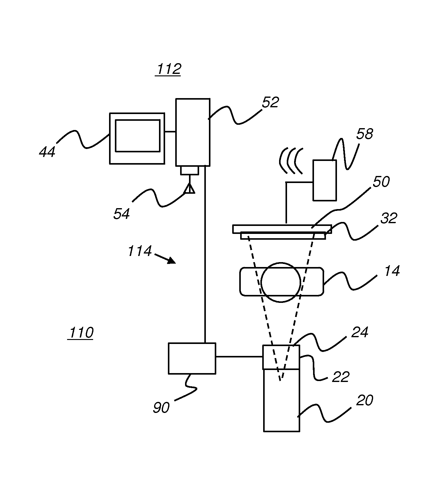
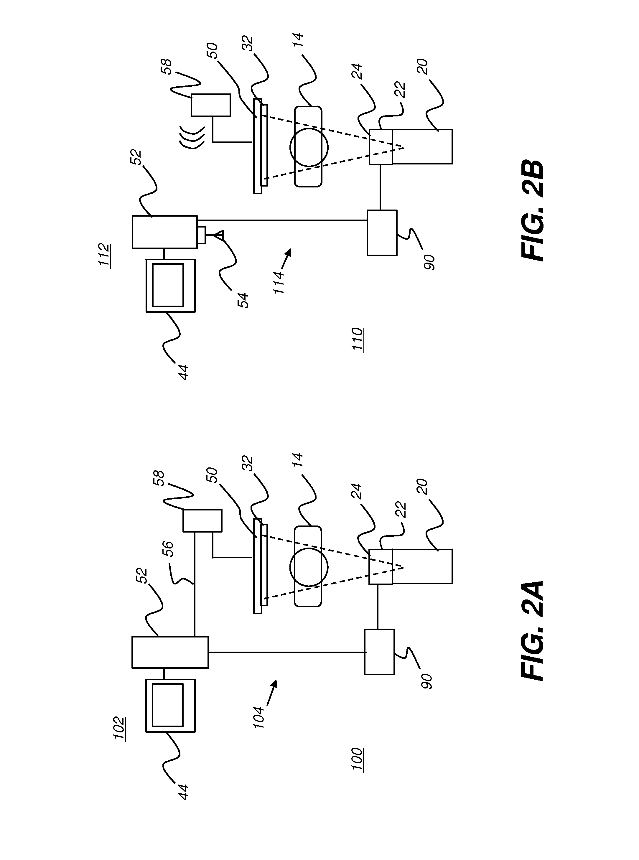
[0063]The following is a detailed description of the preferred embodiments of the invention, reference being made to the drawings in which the same reference numerals identify the same elements of structure in each of the several figures.

[0064]Where they are used, the terms “first”, “second”, and so on, do not necessarily denote any ordinal, sequential, or priority relation, but are simply used to more clearly distinguish one element or set of elements from another, unless specified otherwise. The term “pixel” has its standard meaning, referring to a picture element, expressed as a unit of image data.

[0065]In the context of the present disclosure, the terms “viewer”, “operator”, and “user” are considered to be equivalent and refer to the viewing practitioner or other person who views and manipulates an x-ray image, such as a fluoroscopic image, on a display monitor. A “viewer instruction” can be obtained from explicit commands entered by the viewer on the surface of the display or m...


PUM


Abstract

A method for defining the shape of a radiation beam that is directed toward a subject and to a free-standing imaging detector detects the position and orientation of the imaging detector relative to a radiation source, then adjusts an aperture that lies in the path of the radiation beam to shape the beam for incidence on a predetermined area of the detector according to the detected imaging detector position. The radiation source is energized to emit the shaped radiation beam and the image data about the subject is acquired from the imaging detector.

Description

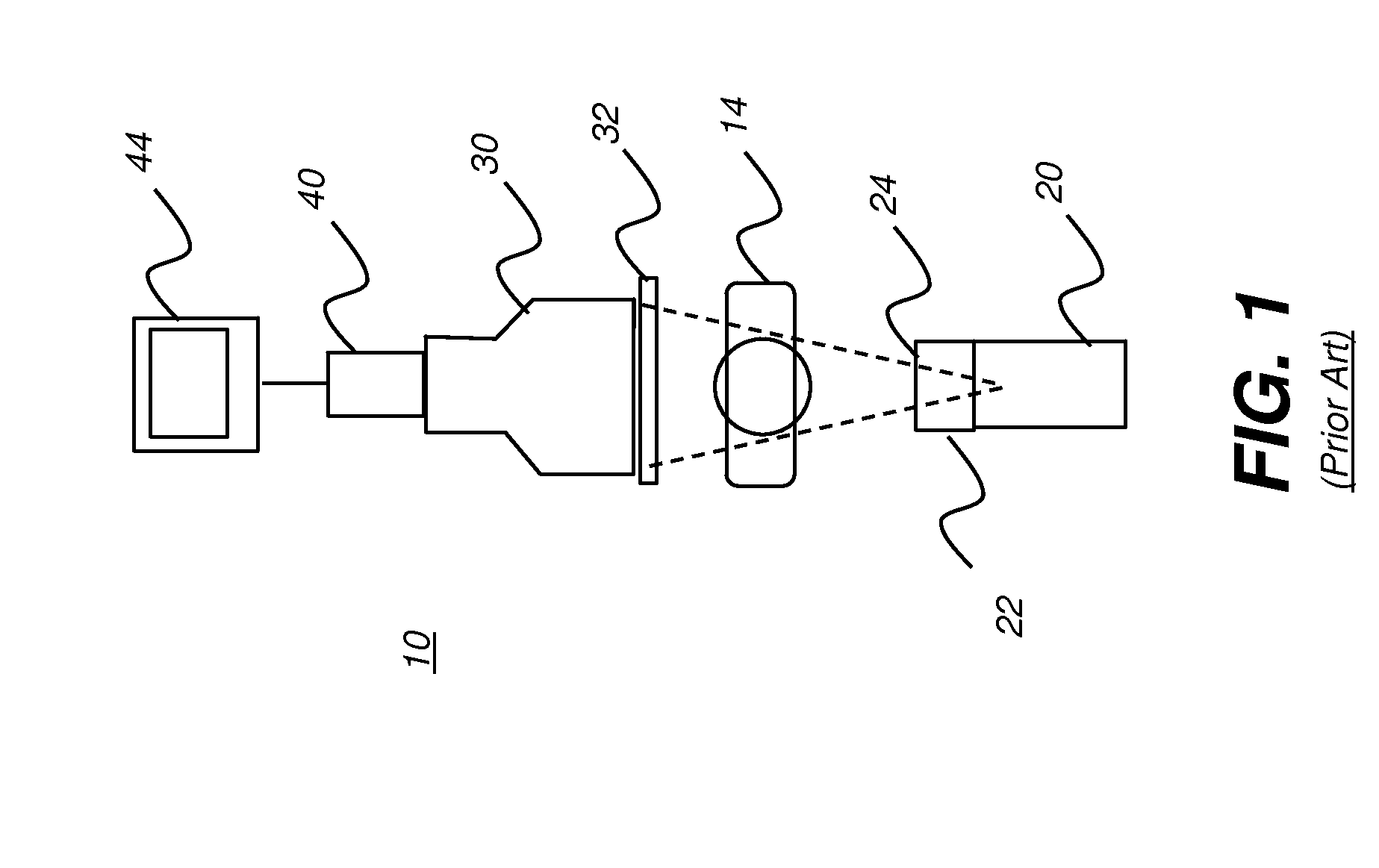
FIELD OF THE INVENTION[0001]The invention relates generally to the field of medical imaging; more particularly to a method for control of components of a portable x-ray fluoroscopic imaging apparatus with a detachable x-ray detector.BACKGROUND OF THE INVENTION[0002]Fluoroscopy provides near real-time visualization of internal anatomy of a patient, with the ability to monitor dynamic processes, including tracking the relative motion of various types of features such as probes or other devices, fluids, and structures. Fluoroscopy is used, for example to help in diagnosis and to position the patient for subsequent image recording or to position and manipulate various types of devices for interventional procedures.[0003]The block diagram of FIG. 1 shows components in the imaging path of a conventional fluoroscopy system 10 for obtaining images of a patient 14 or other subject. Radiation from an x-ray source 20 that typically uses a collimator 22 and filtration 24 is directed through a p...

Claims


Application Information

Patent Timeline
Patent Type & Authority Applications(United States)
IPC IPC(8): A61B6/00
CPCA61B6/4411A61B6/487A61B6/4405A61B6/4441A61B6/464A61B6/547A61B6/06A61B6/4007A61B6/4021A61B6/4233A61B6/4283A61B6/467A61B6/481A61B6/542A61B6/56A61B6/563A61B6/587A61B6/588G21K1/046
Inventor SEHNERT, WILLIAM J.RICHARD, SAMUELYORKSTON, JOHNWANG, XIAOHUI
Owner CARESTREAM HEALTH INC
Why Eureka
Try Eureka