
Wellbore desanding system

a technology of oil wells and production fluids, which is applied in the direction of machines/engines, borehole/well accessories, liquid fuel engines, etc., can solve the problems of limiting the productivity of wells, prone to produce significant quantities of sand, and the upward velocity of the production fluids in the wellbore is not sufficient to lift the sand, so as to reduce the pressure

Inactive Publication Date: 2015-08-13
NAT OILWELL VARCO LP
View PDF0 Cites 19 Cited by
  • Summary
  • Abstract
  • Description
  • Claims
  • Application Information

AI Technical Summary

Benefits of technology

The wellbore desanding system described in the patent text has a discharge port that allows fluids to be directed to the appropriate pressure that is required to operate the system. This alternative method eliminates the need for a flow splitting device and a pressure reduction device. The system includes a fluidizing device and a pump that works together to remove sand and other debris from the wellbore. The pump has a stator section and a rotor section, with the rotor section receiving production fluid from the well and feeding it through a supply duct to the fluidizing device. This system provides an effective and efficient way to remove sand and debris from wellbores.

Problems solved by technology

These wells may be produced without sand screens or other forms of downhole sand control that would limit the wells' productivity.
As a result, wells of this type are prone to produce significant quantities of sand.
In many cases, the upward velocity of the production fluids in the wellbore is not sufficient to lift the sand with the fluid production, and a portion of the sand settles to the bottom of the well.
It is impossible to install and operate a pressurized container within a wellbore that could be loaded and then sealed in this manner.
In addition, there is the added challenge and cost of providing a separate water supply conduit from the surface to the TORE.

Method used


Image

  • Wellbore desanding system
  • Wellbore desanding system
  • Wellbore desanding system

Examples


Embodiment Construction

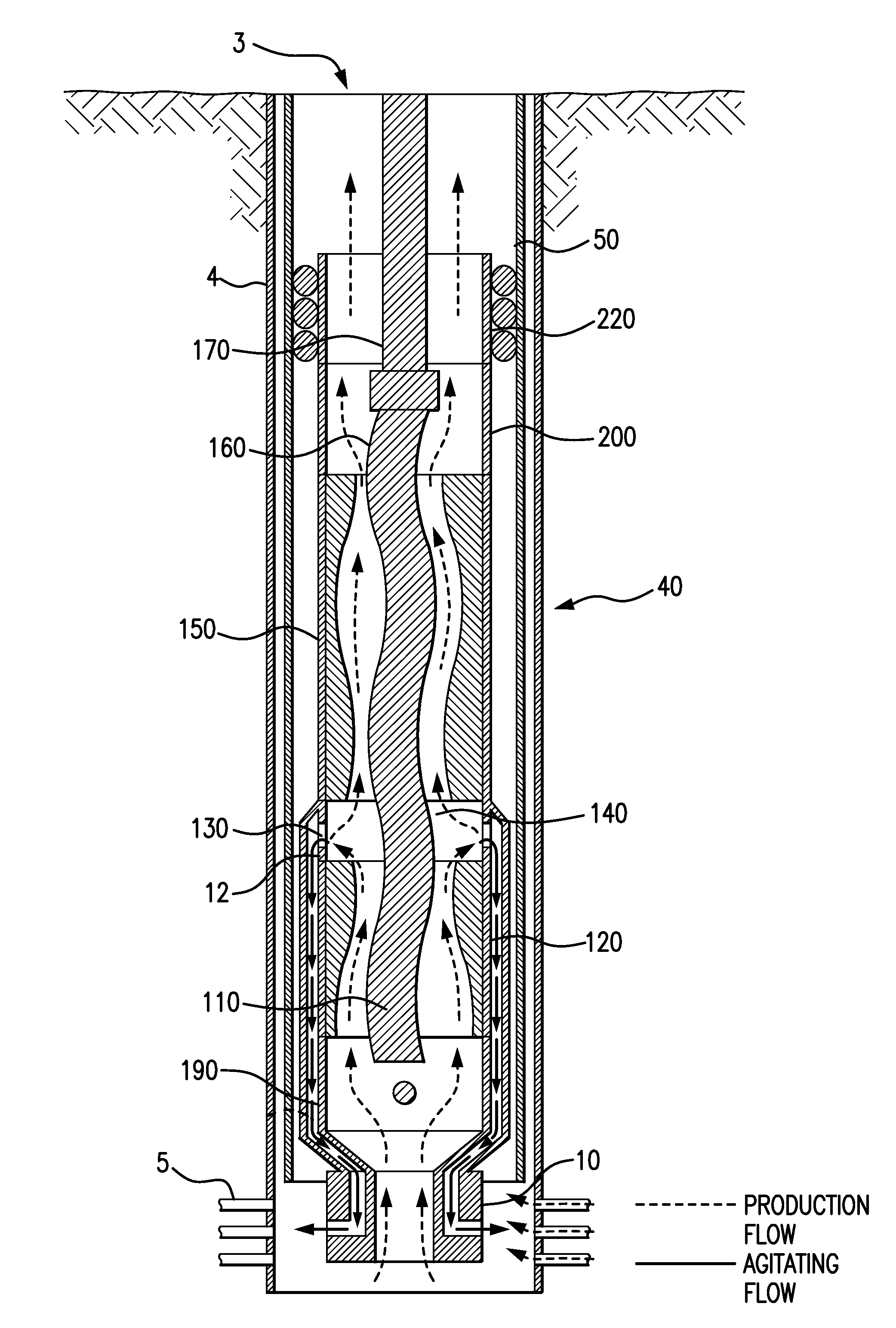
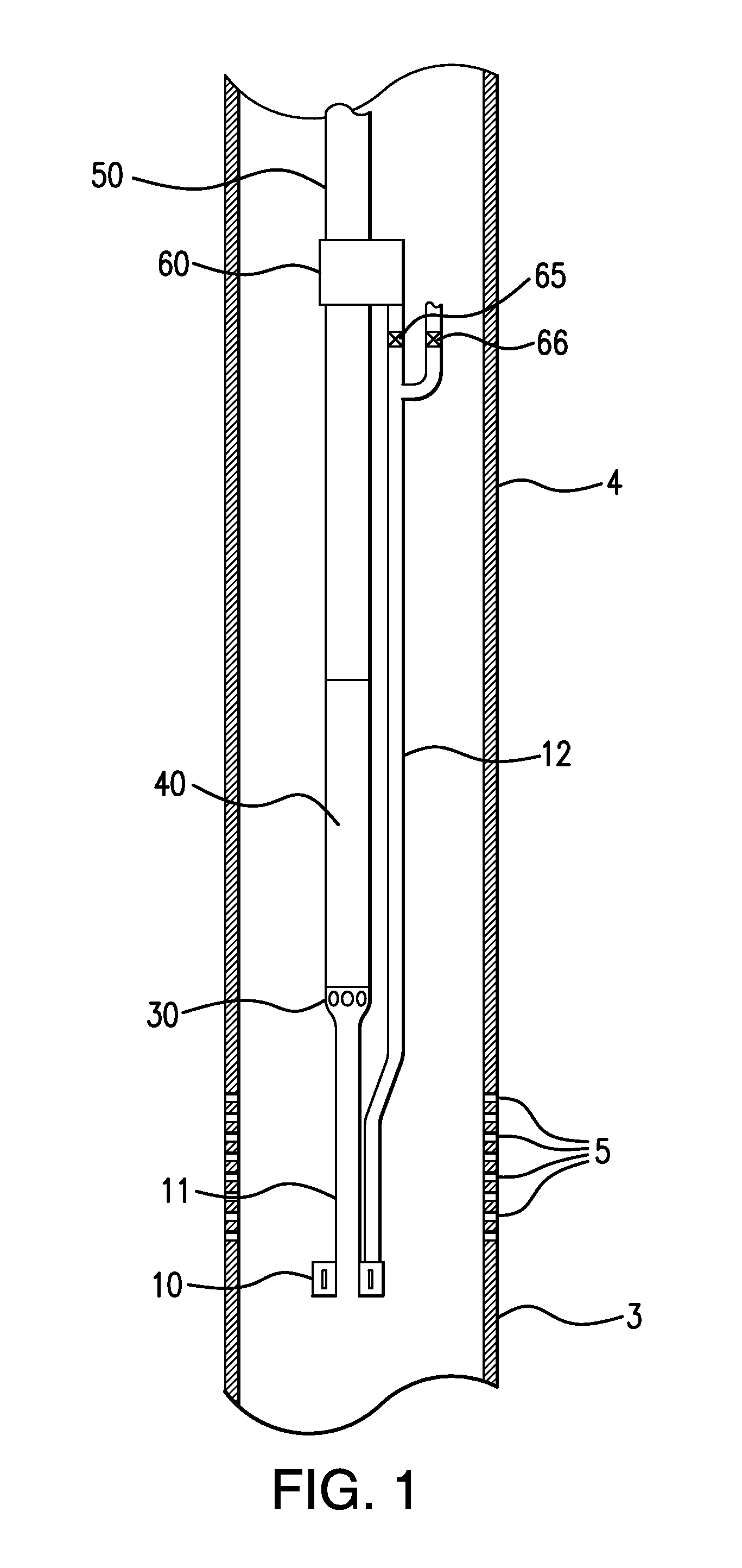
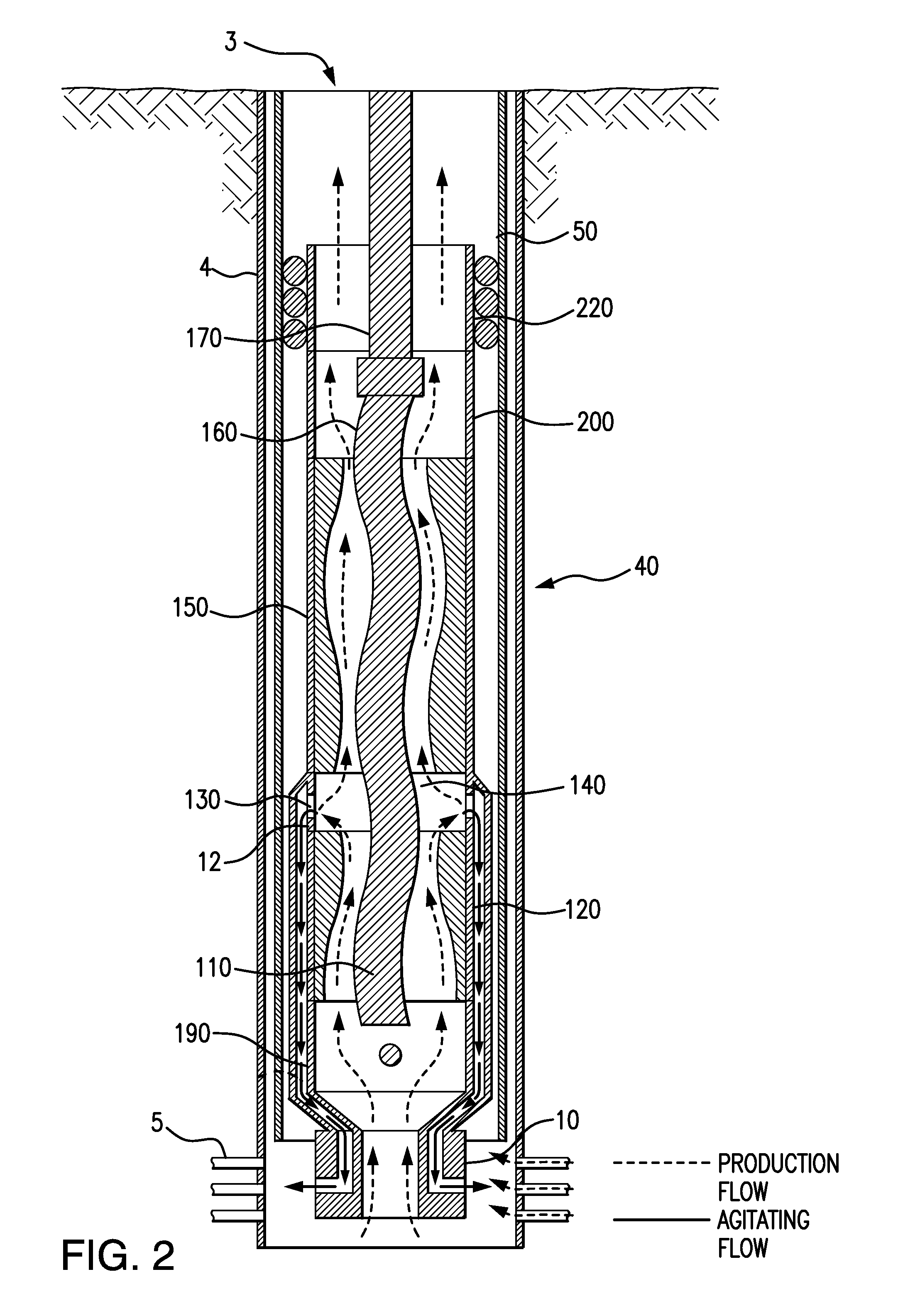
[0028]In accordance with the present invention, a wellbore desanding system is provided that comprises a fluidizing device at the bottom of the well, placed, for example, below the casing perforations in the bottom of the well, to continuously fluidize and lift solids from the well bottom thereby preventing accumulation of solids in the well that can stop the flow of fluids into the well, wherein the fluidizing device is connected to a pump such that the supply duct (water supply conduit for example) is connected to the discharge of the pump and a discharge duct is connected to the suction of the pump. Artificial lift of heavy oil with sand is primarily carried out by progressive cavity pumps or jet pumps. The current invention can be adapted to be used with any type of a downhole pump including progressive cavity and jet pumps.

[0029]Also in accordance with the present invention, a wellbore desanding system is provided that comprises a fluidizing device at the bottom of the well, pl...


PUM


Abstract

The invention relates to system and method for desanding an oil well that includes a fluidizing device (TORE), connected to a downhole pump that connects to a production tubing such that a supply duct is connected to the discharge of the pump and a discharge duct is connected to the suction of the pump. Embodiments include a pressure balance transition device between the TORE and the pump and / or a flow splitting device in the production tubing after the discharge of the pump. Other embodiments relate to a system and method for desanding an oil well in which a fluidizing unit is connected to a pump such that the supply duct is connected to an opening in the pump body or pump rotor and a discharge duct is connected to the suction of the pump. If connected to the rotor, the supply duct is integral to the pump rotor.

Description

FIELD OF THE INVENTION[0001]The present invention generally relates to a method and system for desanding an oil well by hydrodynamically fluidizing liquid and solid mixtures in said well and transporting them to the surface. More specifically, the invention relates to a method and system for adapting TORE solids fluidizing technology to remove accumulated solids from a producing wellbore.BACKGROUND OF THE INVENTION[0002]Wells that produce heavy oil from low pressure reservoirs require some form of artificial lift, such as pumping for example, from the bottom of the wellbore to raise the fluids to the surface. These wells may be produced without sand screens or other forms of downhole sand control that would limit the wells' productivity. As a result, wells of this type are prone to produce significant quantities of sand. In many cases, the upward velocity of the production fluids in the wellbore is not sufficient to lift the sand with the fluid production, and a portion of the sand ...

Claims


Application Information

Patent Timeline
Patent Type & Authority Applications(United States)
IPC IPC(8): E21B43/12
CPCE21B43/121E21B43/126E21B37/00F04C13/00F04C2/1071F04C13/008
Inventor WOLF, MARK E.AHMED, TARIQTHOMAS, GARETH DAVID
Owner NAT OILWELL VARCO LP
Learn More