Supercharge Your Innovation With Domain-Expert AI Agents!

Measurement circuitry and method for measuring a clock node to output node delay of a flip-flop

a clock node and measurement circuit technology, applied in the direction of pulse characteristics measurement, pulse technique, instruments, etc., can solve the problems of not providing any mechanism for compensating for mismatches, no way to compensate mismatch errors, and complex known techniques for measuring the clock to output node delay (hereafter referred to as c-q delay). , to achieve the effect of simple and effective mechanism, easy placement and routing

Active Publication Date: 2015-08-13
ARM LTD +1
View PDF2 Cites 4 Cited by
  • Summary
  • Abstract
  • Description
  • Claims
  • Application Information

AI Technical Summary

Benefits of technology

The present invention relates to a measurement circuitry for accurately measuring the delay of a flip-flop in an integrated circuit. The circuitry uses a reference unit cell with components that produce an indication of delay in the main unit cells during the measurement process. By measuring both the first and second oscillation periods, the circuitry removes the effect of the pulse generation circuitry used in each main unit cell, resulting in more accurate measurements. The circuitry does not require any sophisticated analog circuits and can be easily placed and routed in physical layout. The pulse generation circuitry can be formed in a variety of ways, and the width of the input clock pulse is not critical. The measured clock node to output node delay of the flip-flop can be used to provide characterization data for the flip-flop standard cell, which is useful in designing integrated circuits using standard cell library components.

Problems solved by technology

However, the known techniques for measuring the clock to output node delay (hereafter referred to as the C-Q delay) are typically quite complex, and often require the use of sophisticated analog circuits, such as TDC (Time to Digital Converter) circuits, in order to measure the C-Q delay.
Further, there is no way to compensate mismatch errors that occur due to the extra logic gates.
338-339, 2011, This paper adds many extra logic gates (XOR, MUXs) to a device under test to measure C-Q delays, but does not provide any mechanism for compensating for any mismatches that they introduce.
Accordingly, it will be appreciated that the known techniques are often complex, requiring many additional components, and often custom layouts, and further suffer from inaccuracies due to mismatch errors that can be introduced.

Method used


Image

  • Measurement circuitry and method for measuring a clock node to output node delay of a flip-flop
  • Measurement circuitry and method for measuring a clock node to output node delay of a flip-flop
  • Measurement circuitry and method for measuring a clock node to output node delay of a flip-flop

Examples


Embodiment Construction

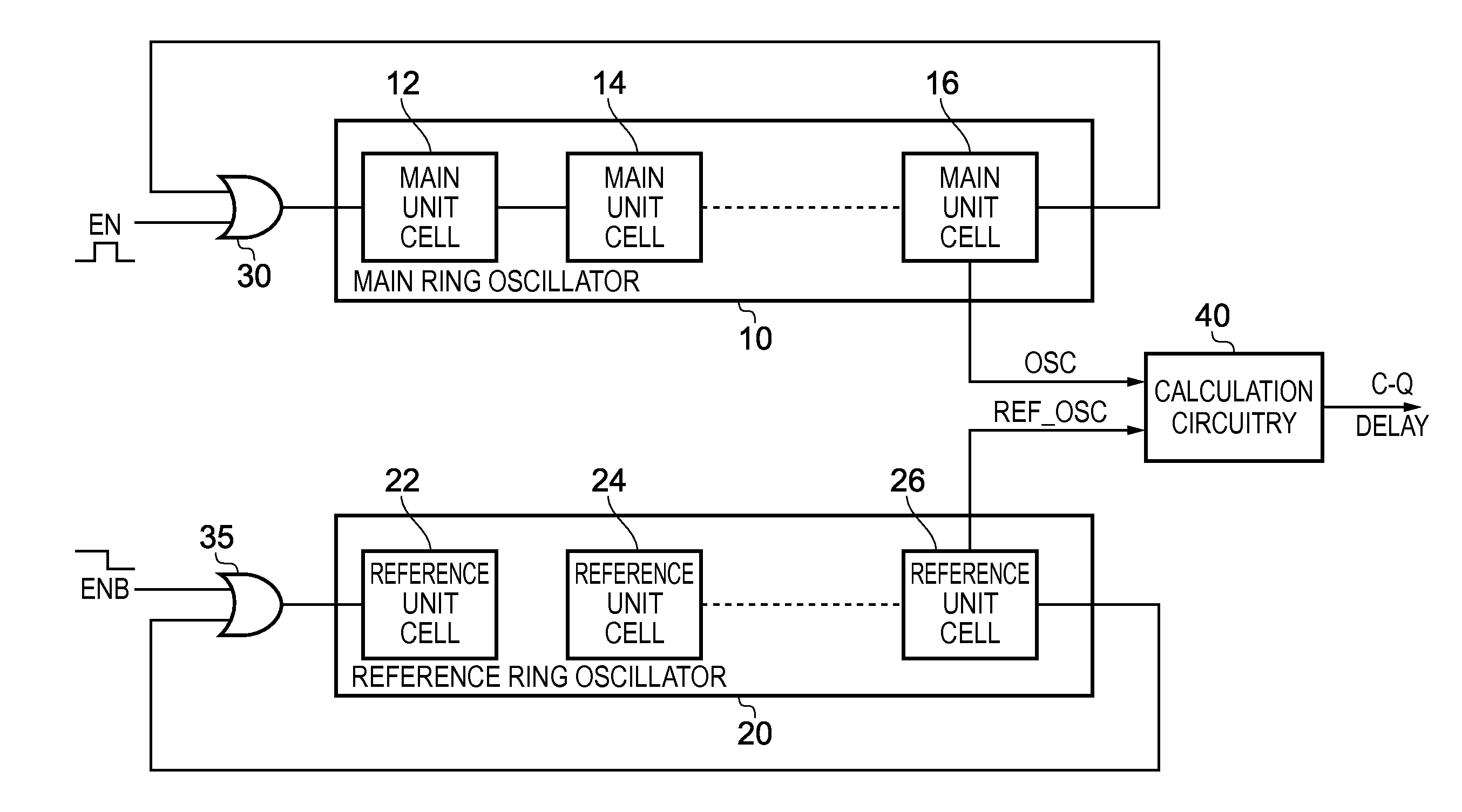
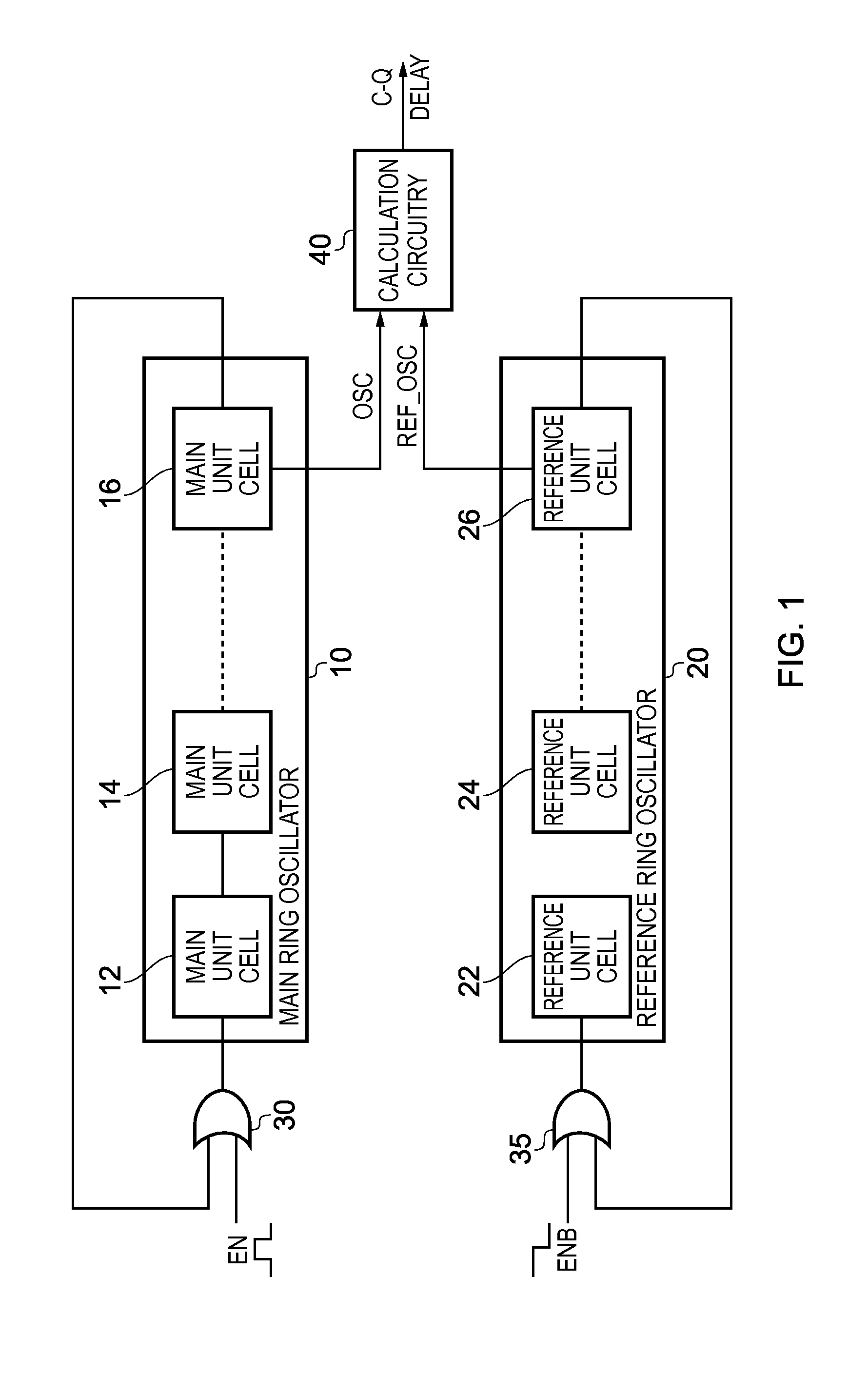
[0036]FIG. 1 is a block diagram schematically illustrating measurement circuitry in accordance with one embodiment. The measurement circuitry comprises a main ring oscillator 10 and a reference ring oscillator 20. The main ring oscillator 10 includes a plurality of main unit cells 12, 14, 16, and similarly the reference ring oscillator 20 includes a plurality of reference unit cells 22, 24, 26. The reference ring oscillator in the embodiment of FIG. 1 is arranged to have the same number of reference unit cells as the number of main unit cells provided in the main ring oscillator. That number can vary dependent on embodiments, but in one embodiment that number N is equal to 4n+2, where n is a positive integer. In one particular embodiment, it has been found that this formulation of N is a requirement to make the reference ring oscillate correctly. However, in other implementations such a restriction may not be required.

[0037]At initialisation time, both the main ring oscillator and t...


PUM


Abstract

A measurement circuit and method are provided for measuring a clock node to output node delay of a flip-flop. A main ring oscillator has a plurality of main unit cells arranged in a ring, with each main unit cell comprising a flip-flop and pulse generation circuitry connected to the output node of the flip-flop. The flip-flop is responsive to receipt of an input clock pulse at the clock node to output a data value transition from the output node, and the pulse generation circuitry then generates from the data value transition an input clock pulse for a next main unit cell in the main ring, whereby the main ring oscillator generates a first output signal having a first oscillation period. A reference ring oscillator has a plurality of reference unit cells arranged to form a reference ring, and generates a second output signal having a second oscillation period, each reference unit cell comprising components configured such that the second oscillation period provides an indication of a propagation delay through the pulse generation circuitry of the main unit cells of the main ring during the first oscillation period. Calculation circuitry then determines the clock node to output node delay of the flip-flop from the first oscillation period and the second oscillation period. This provides a particularly simple and accurate mechanism for calculating the clock node to output node delay of a flip-flop.

Description

BACKGROUND OF THE INVENTION[0001]1. Field of the Invention[0002]The present invention relates to a measurement circuit and method for measuring a clock node to output node delay of a flip-flop.[0003]2. Description of the Prior Art[0004]There are many situations where it is desirable to measure the clock node to output node delay of a flip-flop. For example, such flip-flops will often be used extensively in data processing systems, and when designing such data processing systems it is useful to know the clock to output node delay of the flip-flop, along with information about the delay associated with other circuit components. However, the known techniques for measuring the clock to output node delay (hereafter referred to as the C-Q delay) are typically quite complex, and often require the use of sophisticated analog circuits, such as TDC (Time to Digital Converter) circuits, in order to measure the C-Q delay.[0005]Some known techniques for measuring the C-Q delay are illustrated by...

Claims


Application Information

Patent Timeline
Patent Type & Authority Applications(United States)
IPC IPC(8): G01R31/317H03K3/03
CPCH03K3/0315G01R31/31725
Inventor KIM, YEJOONGSYLVESTER, DENNIS MICHAELBLAAUW, DAVID THEODORECLINE, BRIAN TRACY
Owner ARM LTD
Features
  • R&D
  • Intellectual Property
  • Life Sciences
  • Materials
  • Tech Scout
  • Unparalleled Data Quality
  • Higher Quality Content
  • 60% Fewer Hallucinations
Learn More