
Multi facet mirror of a microlithographic projection exposure apparatus

a technology of exposure apparatus and exposure mirror, which is applied in the direction of photomechanical apparatus, printers, instruments, etc., can solve the problem that it is not generally possible to use lenses or other refractive optical elements in such an apparatus, and achieve the effect of reliable and accurate function of the mirror facet uni

Active Publication Date: 2015-08-13
CARL ZEISS SMT GMBH
View PDF2 Cites 5 Cited by
  • Summary
  • Abstract
  • Description
  • Claims
  • Application Information

AI Technical Summary

Benefits of technology

The patent describes a mirror lift mechanism that allows for fast tilting of a mirror by synchronizing the movements of the lifting member and the displacement member. The actuators act on the opposite side of the mirror substrate, making it possible to keep the actuator small. A rest member surrounds the displacement member, ensuring reliable and accurate function of the mirror facet unit. The technical effect is a more efficient and accurate mirror lift mechanism.

Problems solved by technology

Because there are generally no optical materials available that are transparent for EUV light, it is not generally possible to use lenses or other refractive optical elements in such an apparatus.

Method used


Image

  • Multi facet mirror of a microlithographic projection exposure apparatus
  • Multi facet mirror of a microlithographic projection exposure apparatus
  • Multi facet mirror of a microlithographic projection exposure apparatus

Examples


Embodiment Construction

I.

General Construction of Projection Exposure Apparatus

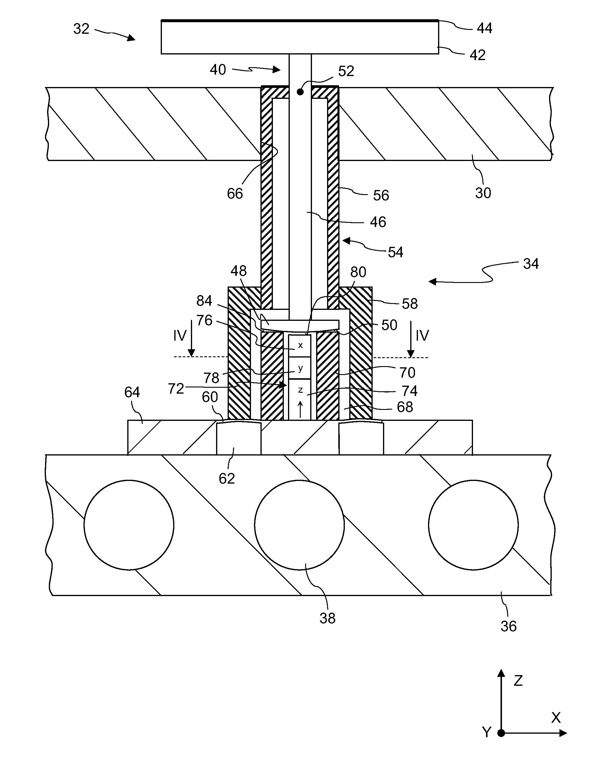
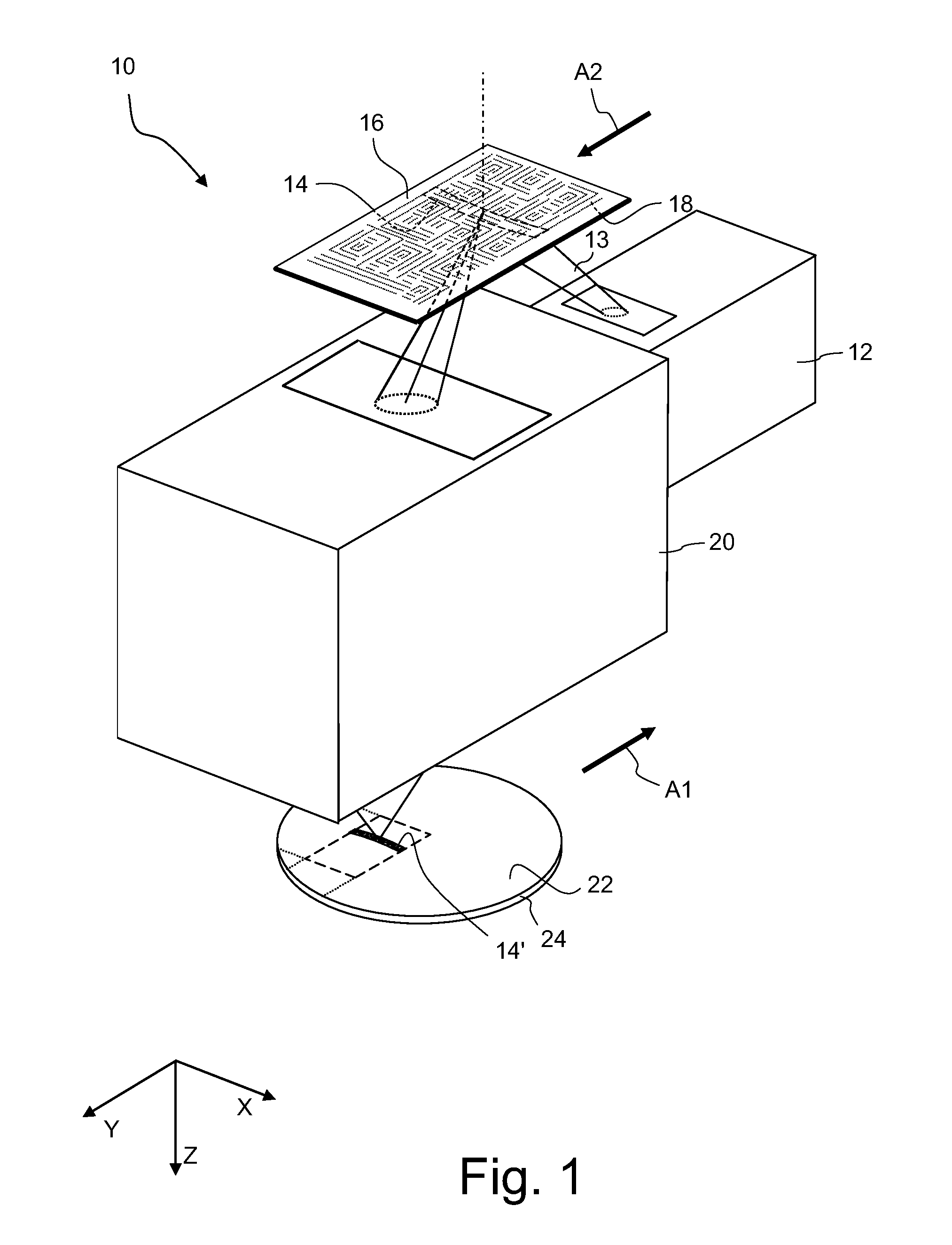
[0049]FIG. 1 is a perspective and highly simplified view of a EUV projection exposure apparatus 10 which is designed in accordance with the present disclosure. The apparatus 10 includes an illumination system 12 which produces a beam 13 of projection light that has a wavelength in the EUV spectral range, for example 13.4 nm. The beam 13 illuminates from below a field 14 on a mask 16 which contains on its underside a reflective pattern 18 formed by a plurality of small features. In this embodiment the illuminated field 14 has the shape of a ring segment.

[0050]A projection objective 20 images the pattern 18 within the illuminated field 14 onto a light sensitive layer 22 which is supported by a substrate 24. Typically the light sensitive layer 22 is a photoresist and the substrate 24 is a silicon wafer. The substrate 24 is arranged on a wafer stage (not shown) such that a top surface of the light sensitive layer 22 is precisely loc...


PUM

PropertyMeasurementUnit
angleaaaaaaaaaa
wavelengthsaaaaaaaaaa

Abstract

A multi facet mirror of a microlithographic projection exposure apparatus includes a plurality of mirror facet units. Each unit includes a mirror member with a body, a reflective coating provided at one end of the body and an actuating surface provided at an opposite end. The unit further includes a rest member on which the actuating surface rests while the mirror member is not moving, and an actuator that tilts the mirror member about a tilting axis. The actuator has a contact surface and a lifting member which moves the actuating surface along a lifting direction. In a first operating state of the lifting member the actuating surface rests on the rest member and in a second operating state on the contact surface. A displacement member displaces the contact surface along a lateral direction only while the lifting member is in the second operating state.

Description

CROSS-REFERENCE TO RELATED APPLICATIONS[0001]The present application is a continuation of, and claims benefit under 35 USC 120 to, international application PCT / EP2010 / 005195, filed Aug. 25, 2010, the entire contents of which are hereby incorporated by reference in their entirety.FIELD[0002]The disclosure generally relates to a multi facet mirror of a microlithographic projection exposure apparatus. Such mirrors are often used, for example, in the illumination system of next generation EUV apparatus.BACKGROUND[0003]Microlithography (also referred to as photolithography or simply lithography) is a technology for the fabrication of integrated circuits, liquid crystal displays and other microstructured devices. The process of microlithography, in conjunction with the process of etching, is used to produce patterns in thin film stacks that have been formed on a substrate, for example a silicon wafer. At each layer of the fabrication, the wafer is first coated with a photoresist which is...

Claims


Application Information

Patent Timeline
Patent Type & Authority Applications(United States)
IPC IPC(8): G03F7/20G02B26/08G02B5/09G02B5/08
CPCG03F7/702G02B5/09G02B26/0816G02B5/0891G03F7/70075G03F7/70825G03F7/70141
Inventor RASSEL, THORSTENHAUF, MARKUS
Owner CARL ZEISS SMT GMBH
Learn More