Acoustic transducer

a transducer and acoustic technology, applied in the direction of transducer diaphragms, semiconductor electrostatic transducers, transducer types, etc., can solve problems such as mute phenomena, and achieve the effects of preventing the projection from separating, preventing an interval between projections from increasing, and preventing mute phenomena

Active Publication Date: 2015-08-13
MMI SEMICON CO LTD
View PDF1 Cites 17 Cited by
  • Summary
  • Abstract
  • Description
  • Claims
  • Application Information

AI Technical Summary

Benefits of technology

The present invention relates to an improved design for an acoustic transducer that prevents separation of its components during operation and avoids issues related to variations in process parameters such as pneumatic pressure and temperature. This results in better performance with reduced noise levels and increased efficiency. Additionally, the design includes features like anti-muting properties that improve overall quality of sound produced by the device.

Problems solved by technology

The technical problem addressed in this patent is how to prevent the occurrence of the mute phenomena such as incomplete closure of the diaphragm due to strong windblow or static forces during operation of the acoustic sensor. It proposes various methods including arranging protons or pins at different positions on the chip or increasing the size of the openings but all these solutions come with their own limitations and drawbacks.

Method used


Image

  • Acoustic transducer
  • Acoustic transducer
  • Acoustic transducer

Examples


embodiment 1

Modification of Embodiment 1

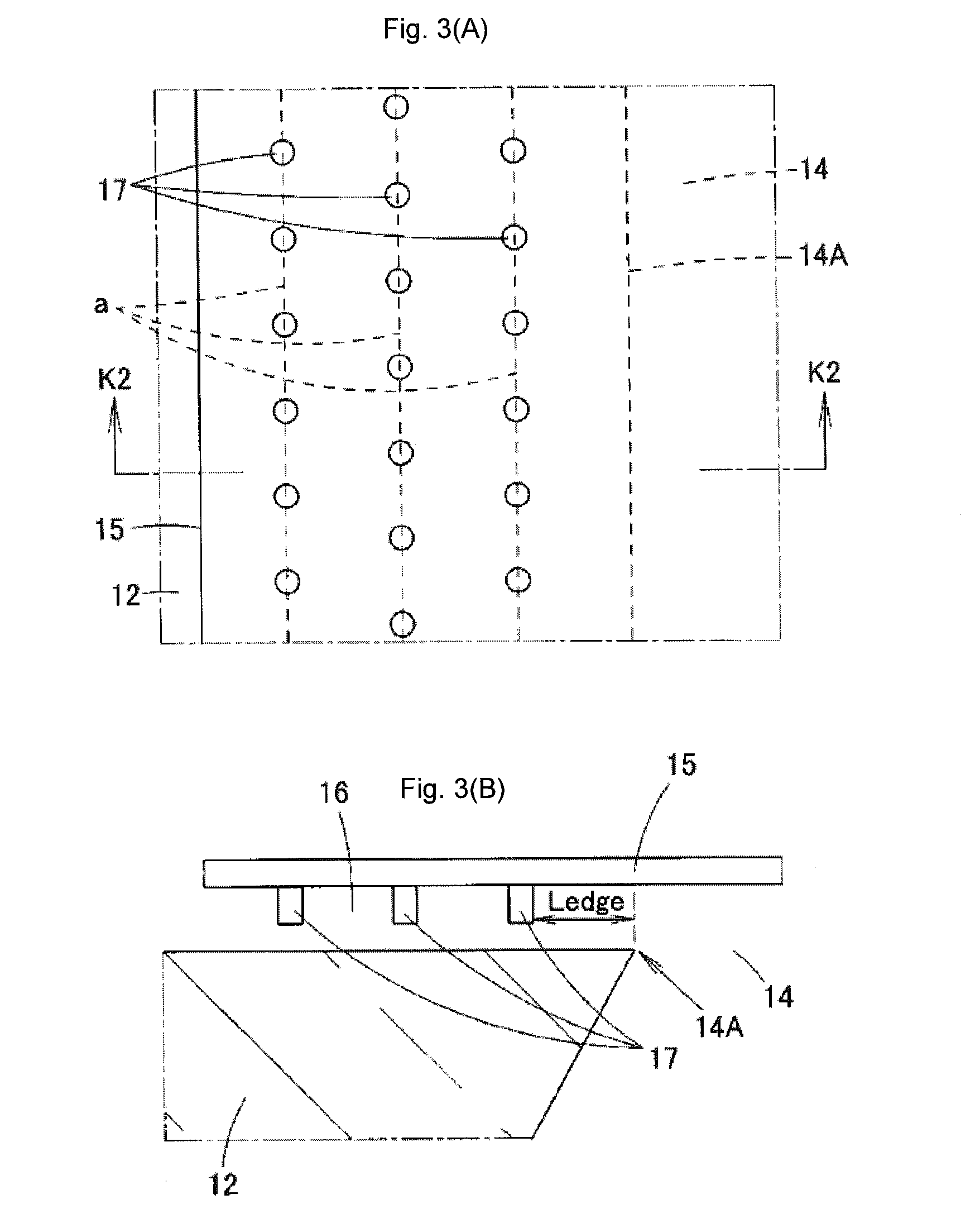
[0084]In the acoustic sensor of the above Embodiment 1, the projections in each array are arrayed in a zigzag manner. However, the projections in a part of arrays may be arrayed in a zigzag manner.

[0085]FIG. 16 illustrates a modification of Embodiment 1 of the present invention. FIG. 16 is an enlarged view of a part of the outer edge of a diaphragm 33. In this modification, only projections 42 in an array located nearest to the edge 38A of an opening 38 are arrayed in a zigzag manner. More specifically, in the array of the projections 42 located nearest to the edge 38A of the opening 38, the positions of every third projections 42 are sifted to a side close to the edge 38A of the opening 38, on the basis of the array of the projections as illustrated in FIG. 3(A).

[0086]According to such a modification, a distance Ledge between the projections 42 located nearest to the edge 38A of the opening 38 and the edge 38A of the opening 38 is shortened compared to a...

embodiment 2

[0088]FIG. 18(A) is a plan view illustrating the arrangement of projections in an acoustic sensor of Embodiment 2 of the present invention. FIG. 18(B) is a sectional view of FIG. 18(A). In Embodiment 2, projections 42 in two or more arrays counted from the end on a side far from the edge 33A of a diaphragm 33 are arrayed in a zigzag manner. Additionally, the array of the projections 42 located farthest from the edge 33A of the diaphragm 33 is located above an opening 38 across the edge 38A of the opening 38. Accordingly, the edge 38A of the opening 38 is located between the array of the projections 42 located farthest from the diaphragm 33 and the array of the projections 42 located second farthest, as viewed from a direction perpendicular to the upper surface of the diaphragm 33.

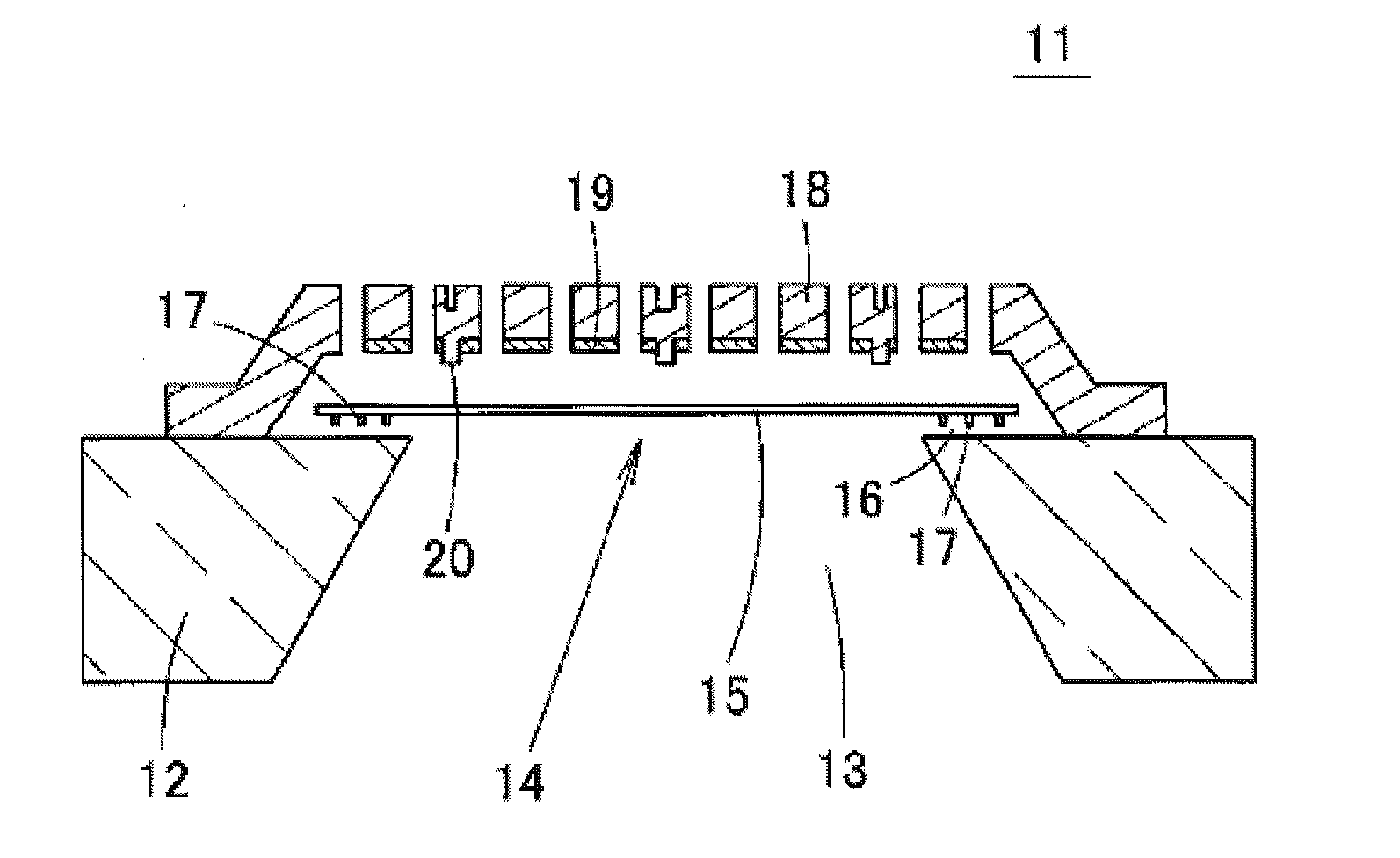
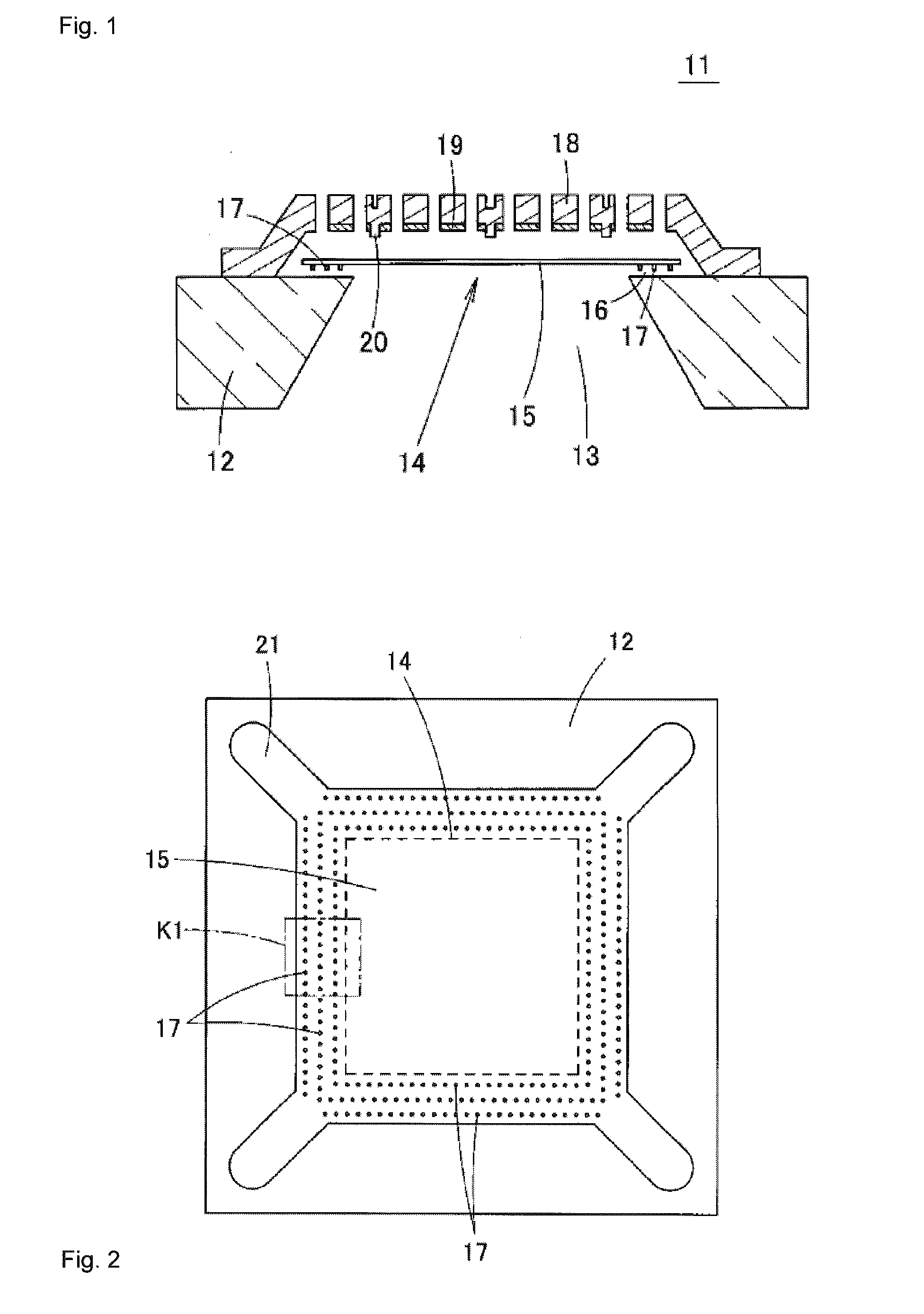
[0089]According to such a structure, it is possible to reliably prevent the occurrence of a mute phenomenon. A chamber 35 of a silicon substrate 32 is opened by etching, and therefore there is a possibility...

embodiment 3

Modification of Embodiment 3

[0092]FIG. 20 is a plan view illustrating the arrangement of projections in a modification of Embodiment 3 of the present invention. In this modification, the array of projections 42 that are arranged on a straight line parallel to the edge 38A of an opening 38, and the arrays of projections 42 that are arrayed on straight lines e obliquely inclined to the edge 38A of the opening 38 are mixed.


PUM


Abstract

An acoustic transducer has a substrate having an opening in an upper surface thereof, a vibration electrode plate disposed above the substrate, and having an outer edge thereof facing the upper surface of the substrate with a gap therebetween, a fixed electrode plate facing the vibration electrode plate, and a plurality of projections protruding on a lower surface of the outer edge of the vibration electrode plate. The vibration electrode plate covers an upper side of the opening. The plurality of projections are disposed so as to not be positioned along a straight line or a curved line parallel to an edge of the opening in at least a part of one or at least two arrays formed on the lower surface of the outer edge.

Description


Claims


Application Information

Patent Timeline
Owner MMI SEMICON CO LTD
Why Eureka
Try Eureka