Devices for controlling the downforce generated by a vehicle

a technology of downforce and vehicle, which is applied in the direction of vehicle body, vehicle sub-unit features, road vehicle drive control system, etc., can solve the problems of increasing drag, increasing drag, and increasing drag, so as to control the downforce generated by the automobil

Active Publication Date: 2015-08-20
MCLAREN AUTOMOTIVE
View PDF39 Cites 46 Cited by
  • Summary
  • Abstract
  • Description
  • Claims
  • Application Information

AI Technical Summary

Benefits of technology

[0014]According to a second aspect of the present invention there is provided: an automobile comprising: a first and a second spoiler provided on the underside of the automobile, the first and second spoilers being positioned symmetrically about the centreline of the automobile, wherein each spoiler is deployable from a respective first position in which, when the automobile is in motion, each spoiler extends minimally into the flow of air beneath the automobile, up to a respective second position in which, when the automobile is in motion, each spoiler extends maximally into the flow of air beneath the automobile so as to reduce the downforce generated by the automobile; and a control unit adapted to receive one or more inputs that indicate the dynamic state of the automobile and select positions of the first and second spoilers between their respective first and second positions, the positions of the first and second spoilers being chosen in dependence on the said dynamic state so as to control the downforce generated by the automobile, wherein if the inputs indicate that the automobile is cornering, the positions of the first and second spoilers are selected so as to counter roll of the automobile.
[0059]Preferably the automobile further comprises: a second spoiler positioned on the underside of the automobile, the second spoiler being deployable from a first position up to a second position such that the second duct can only provide a path for the air to flow from the relatively high pressure region to the region beneath the automobile through second duct when the second spoiler is deployed from its first position, the control unit being configured to, when the automobile is in motion, position the second spoiler between the first and second positions of the spoiler so as to control the downforce generated by the automobile.

Problems solved by technology

In practical situations, it is often the case that an increase in downforce (by, for example, adding spoilers to the vehicle) is accompanied by an increase in drag, meaning that a vehicle set-up to generate high levels of downforce will be compromised by a reduction in its maximum straight line speed.
However, increasing the downforce can lead to an increase in drag which compromises the straight line speed of the vehicle and increases its fuel consumption.
Furthermore at very high speeds the downforce generated may overload the vehicle and result in significant changes in aerodynamic stability under different dynamic conditions, making the vehicle difficult to control.

Method used


Image

  • Devices for controlling the downforce generated by a vehicle
  • Devices for controlling the downforce generated by a vehicle
  • Devices for controlling the downforce generated by a vehicle

Examples


Embodiment Construction

[0073]The apparatus described below provides a means for actively controlling the amount of downforce generated by a vehicle.

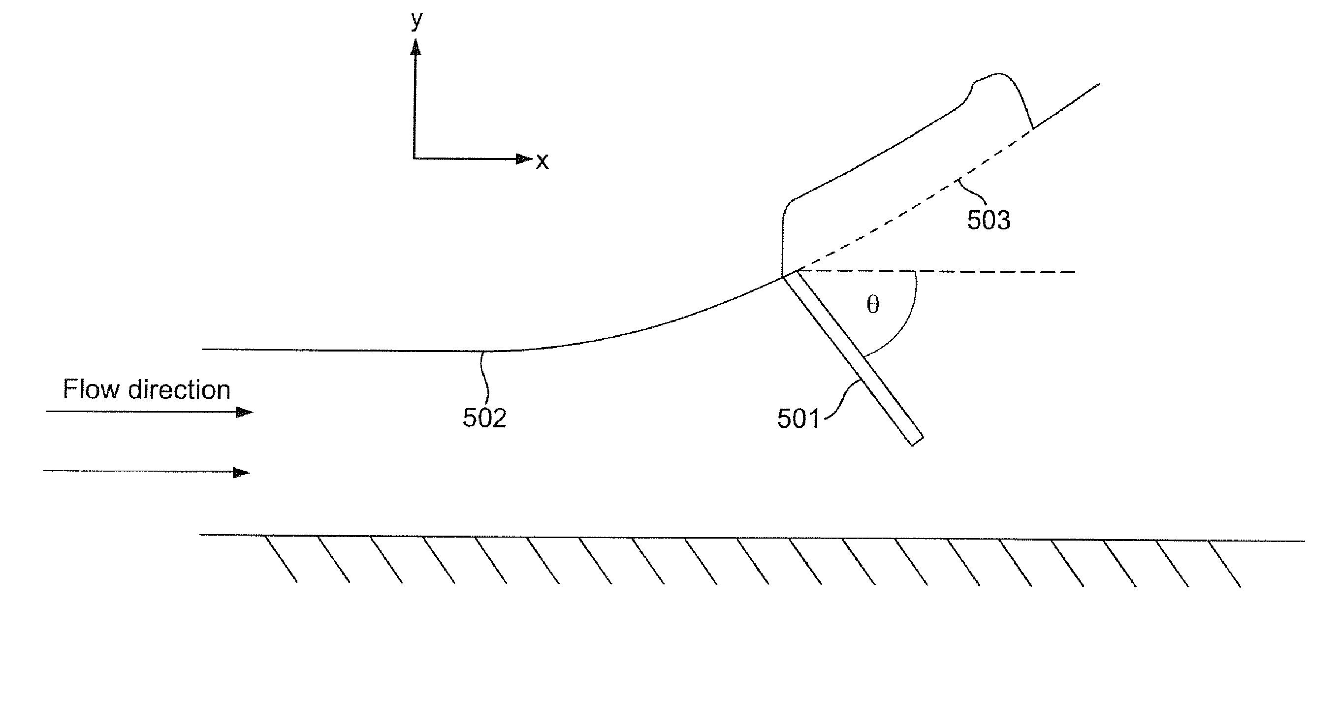
[0074]FIG. 5 shows a system for use in controlling the downforce generated by a vehicle in accordance with a first aspect of the present invention. A flap 501 is attached to a lower surface of a vehicle 502. In the example configuration shown in FIG. 5 the vehicle is travelling in the negative x-direction so that the airflow, taken in the frame of reference of the vehicle, is in the positive x-direction. The flap is deployable from a stowed position shown by the dotted line 503 to a deployed position. The deployed position could be any position between the stowed position and a maximum deployed position. In this example when the flap is in the stowed position it is substantially flush with the underside surface of the vehicle. In alternative examples the flap may not be flush with the underside surface of the vehicle when in its stowed position. When the flap ...


PUM


Abstract

A vehicle comprising a flap that is attached to the vehicle in such a way as to permit movement of the flap from a first position to a second position, wherein the flap is configured to alter the downforce generated by the vehicle when the vehicle is in motion by affecting the airflow underneath the vehicle, the effect of the flap on the airflow being dependent upon the second position of the flap.

Description

FIELD OF DISCLOSURE[0001]This invention relates to an apparatus for use in controlling the downforce generated by a vehicle.BACKGROUND[0002]Guide pins precisely locate and align stacked or mating panels and chasses commonly used with electronics equipment by merging with a punched or drilled hole of an adjacent panel. They install in metallic panels and mate with metallic or fiberglass panels such as printed circuit boards. However, it would be desirable to have a guide pin that is useful for mating multiple panels.[0003]The downforce generated by a vehicle can have a substantial effect on the cornering and braking capability of the vehicle. In practical situations, it is often the case that an increase in downforce (by, for example, adding spoilers to the vehicle) is accompanied by an increase in drag, meaning that a vehicle set-up to generate high levels of downforce will be compromised by a reduction in its maximum straight line speed.[0004]FIG. 1 is a schematic diagram of the ai...

Claims


Application Information

Patent Timeline
Patent Type & Authority Applications(United States)
IPC IPC(8): B62D35/02B60T5/00G05D3/00
CPCB62D35/02B60T5/00G05D3/00B60T1/16B62D35/005B62D37/02B62D35/00B60K11/04B60K11/08B60K11/085B60Y2300/0453B60Y2300/0457B60Y2306/05F15D1/10
Inventor PARRY-WILLIAMS, DANSLIGHT, ARTHUR
Owner MCLAREN AUTOMOTIVE
Why Eureka
Try Eureka