Aircraft for vertical take-off and landing with two wing arrangements

a technology for vertical take-off and landing, applied in the direction of aircraft, vertical landing/take-off aircraft, transportation and packaging, etc., can solve the problem that the propeller may have the disadvantage of the aircraft travel fligh

Inactive Publication Date: 2015-08-20
REITER JOHANNES
View PDF4 Cites 51 Cited by
  • Summary
  • Abstract
  • Description
  • Claims
  • Application Information

AI Technical Summary

Benefits of technology

[0005]It may be an object of the present invention to provide an efficient aircraft for vertical take-off and landing with proper flight conditions.

Problems solved by technology

Propellers may have the disadvantage in travel flight of an aircraft due to a high drag.

Method used


Image

  • Aircraft for vertical take-off and landing with two wing arrangements
  • Aircraft for vertical take-off and landing with two wing arrangements
  • Aircraft for vertical take-off and landing with two wing arrangements

Examples


Embodiment Construction

[0075]The illustration in the drawing is schematically. It is noted that in different figures, similar or identical elements are provided with the same reference signs.

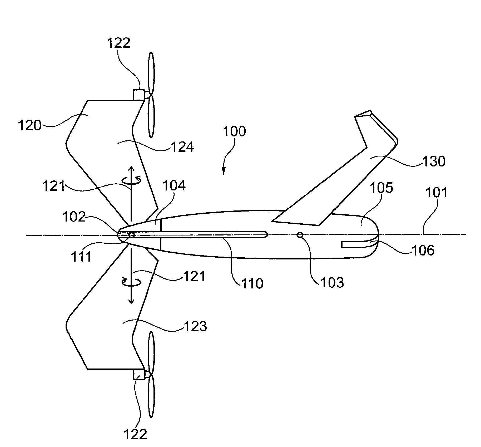
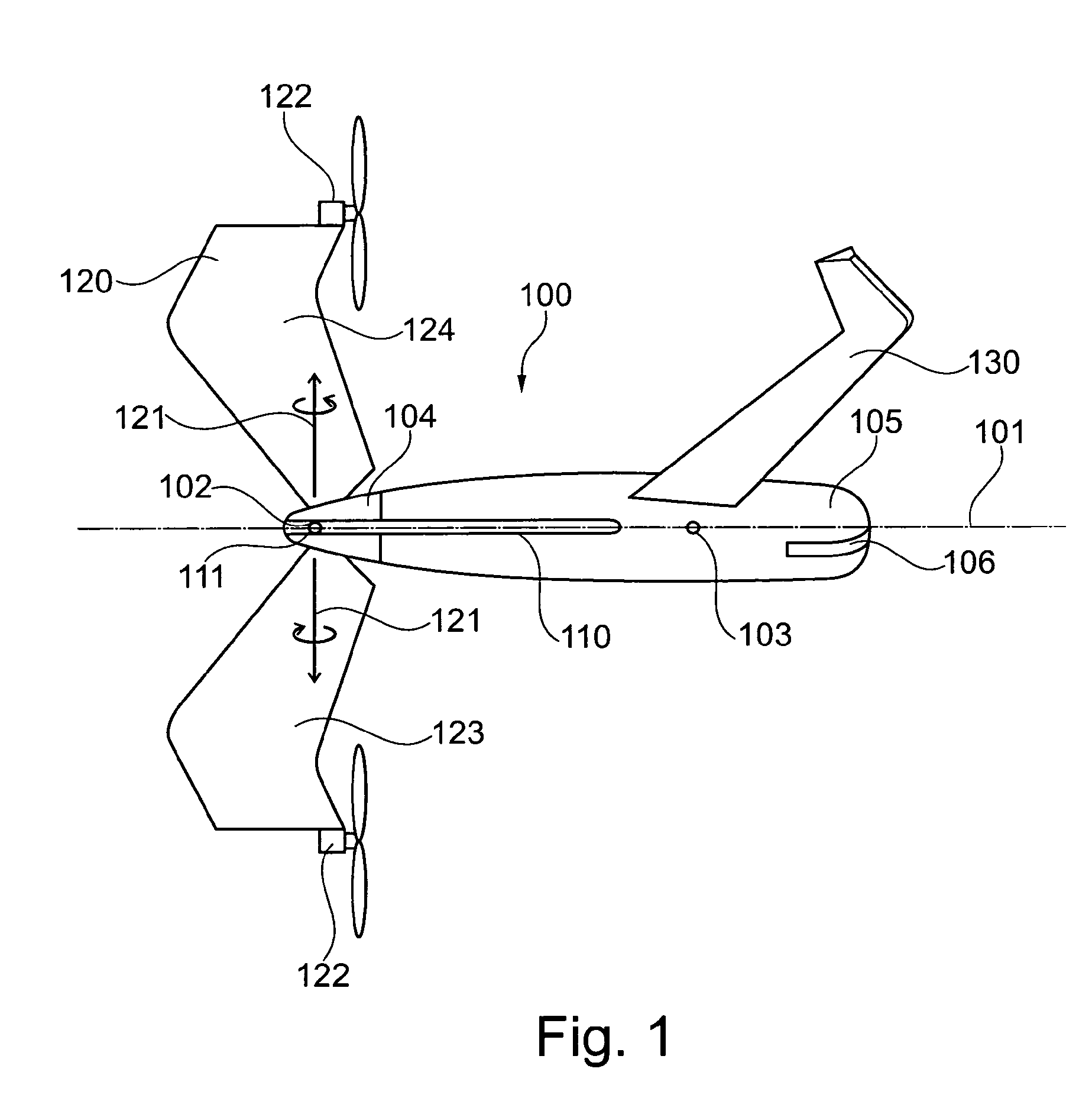
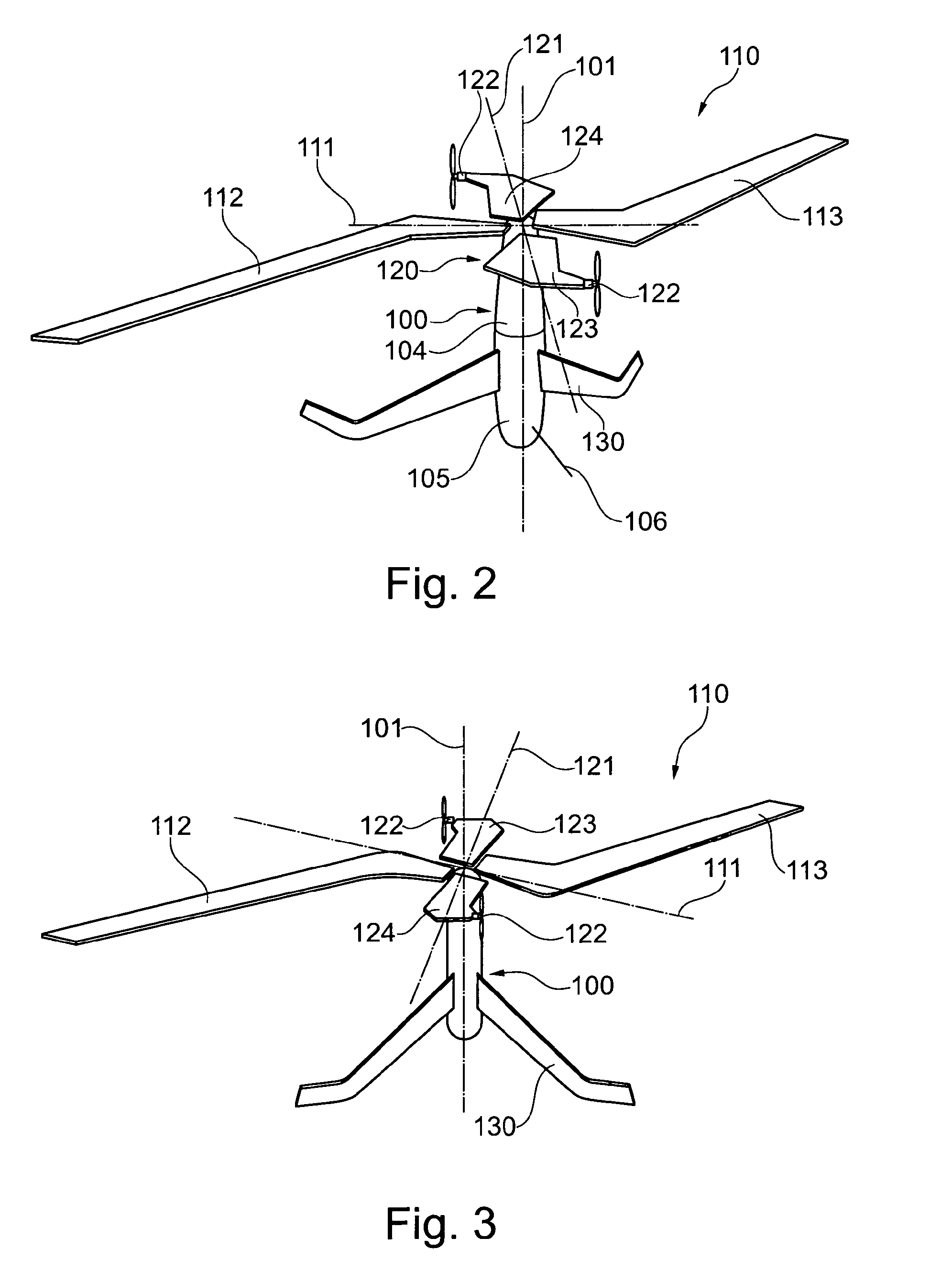
[0076]FIG. 1 shows an aircraft which comprises a fuselage 100 having a fuselage axis 101, a first wing arrangement 110 and a second wing arrangement 120. The first wing arrangement 110 is mounted to the fuselage 100 such that the first wing arrangement 110 is tiltable around a first longitudinal wing axis 111 of the first wing arrangement 110 and such that the first wing arrangement 110 is rotatable around the fuselage axis 101.

[0077]The second wing arrangement 120 comprises at least one propulsion unit 122, wherein in particular the first wing arrangement 110 is free of any propulsion units 122. The second wing arrangement 120 is mounted to the fuselage 100 such that the second wing arrangement 120 is tiltable around a second longitudinal wing axis 121 of the second wing arrangement 120 and such that the second wing ...


PUM


Abstract

The present invention relates to an aircraft comprising a fuselage (100) comprising a fuselage axis (101), a first wing arrangement (110) and a second wing arrangement (120). The first wing arrangement (110) is mounted to the fuselage (100) such that the first wing arrangement (110) is tiltable around a first longitudinal wing axis (111) of the first wing arrangement (110) and such that the first wing arrangement (110) is rotatable around the fuselage axis (101). The second wing arrangement (120) comprises at least one propulsion unit (122), wherein the second wing arrangement (120) is mounted to the fuselage (100) such that the second wing arrangement (120) is tiltable around a second longitudinal wing axis (121) of the second wing arrangement (120) and such that the second wing arrangement (120) is rotatable around the fuselage axis (101). The first wing arrangement (110) and the second wing arrangement (120) are adapted in such a way that, in a fixed-wing flight mode, the first wing arrangement (110) and the second wing arrangement (120) do not rotate around the fuselage axis (101). The first wing arrangement (110) and the second wing arrangement (120) are further adapted in such a way that, in a hover flight mode, the first wing arrangement (110) and the second wing arrangement (120) are tilted around the respective first longitudinal wing axis (111) and the respective second longitudinal wing axis (121) with respect to its orientations in the fixed-wing flight mode and that the first wing arrangement (110) and the second wing arrangement (120) rotate around the fuselage axis (101).

Description

FIELD OF THE INVENTION[0001]The present invention relates to an aircraft for vertical take-off and landing and to a method for operating an aircraft for vertical take-off and landing.BACKGROUND OF THE INVENTION[0002]It is an aim to have aircraft that are able to start and land without a runway for example. Hence, in the past several developments for so called Vertical Take-Off and Landing aircraft (VTOL) have been done. Conventional VTOL-Aircraft need a vertical thrust for generating the vertical lift. Thrust for vertical take-off may be produced by big propellers or jet engines. Propellers may have the disadvantage in travel flight of an aircraft due to a high drag.[0003]An efficient solution for a hover flight capable aircraft is performed by helicopters, using e.g. a big wing area. In a known system, an aircraft comprises an engine for vertical lifting the aircraft (e.g. a propeller) and e.g. a further engine for generating the acceleration of the aircraft in a travel mode up to ...

Claims


Application Information

Patent Timeline
Patent Type & Authority Applications(United States)
IPC IPC(8): B64C29/00B64C37/00B64C3/38
CPCB64C29/0033B64C37/00B64C3/38B64C27/16B64C27/18B64C29/0075B64C29/02B64C39/008B64C39/024B64U30/12B64U70/80B64U30/10B64U30/20B64U50/13B64C3/385B64C27/00B64C27/001B64C29/00
Inventor REITER, JOHANNES
Owner REITER JOHANNES
Why Eureka
Try Eureka