Optical waveguide sheet, backlight unit, and portable terminal

a technology of optical waveguides and backlight units, applied in mechanical devices, lighting and heating apparatus, instruments, etc., can solve the problems of uneven luminance of liquid crystal display surfaces, etc., to achieve uniform luminance, reduce thickness, and lack of uniform luminance

Active Publication Date: 2015-08-20
KEIWA INCORPORATED
View PDF8 Cites 4 Cited by
  • Summary
  • Abstract
  • Description
  • Claims
  • Application Information

AI Technical Summary

Benefits of technology

[0022]As explained in the foregoing, when the optical waveguide sheet according to the first aspect of the present invention is used in an edge-lit backlight unit, the lack in uniformity of luminance of a liquid crystal display surface can be inhibited and a reduction in thickness can be achieved. Therefore, the edge-lit backlight unit according to the second aspect of the present invention including the optical waveguide sheet according to the first aspect of the present invention, and the portable terminal according to the third aspect of the present invention including the backlight unit enable inhibition of the lack in uniformity of luminance of a liquid crystal display unit, and a reduction in thickness to be achieved.

Problems solved by technology

The present inventors found that when such a liquid crystal display device is used, a drawback arises that luminance of the liquid crystal display surface is uneven (lack in uniformity of luminance).
The present inventors thoroughly investigated the cause of the drawback, and consequently found the back face of the optical waveguide sheet adheres (sticks) to the front face of the reflection sheet or the top plate disposed on the back face side of the optical waveguide sheet, and then rays of light enter the adhering portion, leading to the lack in uniformity of luminance.
Furthermore, due to the annular raised portions being provided around the recessed portions, the optical waveguide sheet can properly inhibit the adhesion at the recessed portions and in the vicinity of the recessed portions, and consequently the lack in uniformity of luminance due to the rays of light scattered by the recessed portion can be favorably inhibited.

Method used


Image

  • Optical waveguide sheet, backlight unit, and portable terminal
  • Optical waveguide sheet, backlight unit, and portable terminal
  • Optical waveguide sheet, backlight unit, and portable terminal

Examples


first embodiment

Portable Terminal

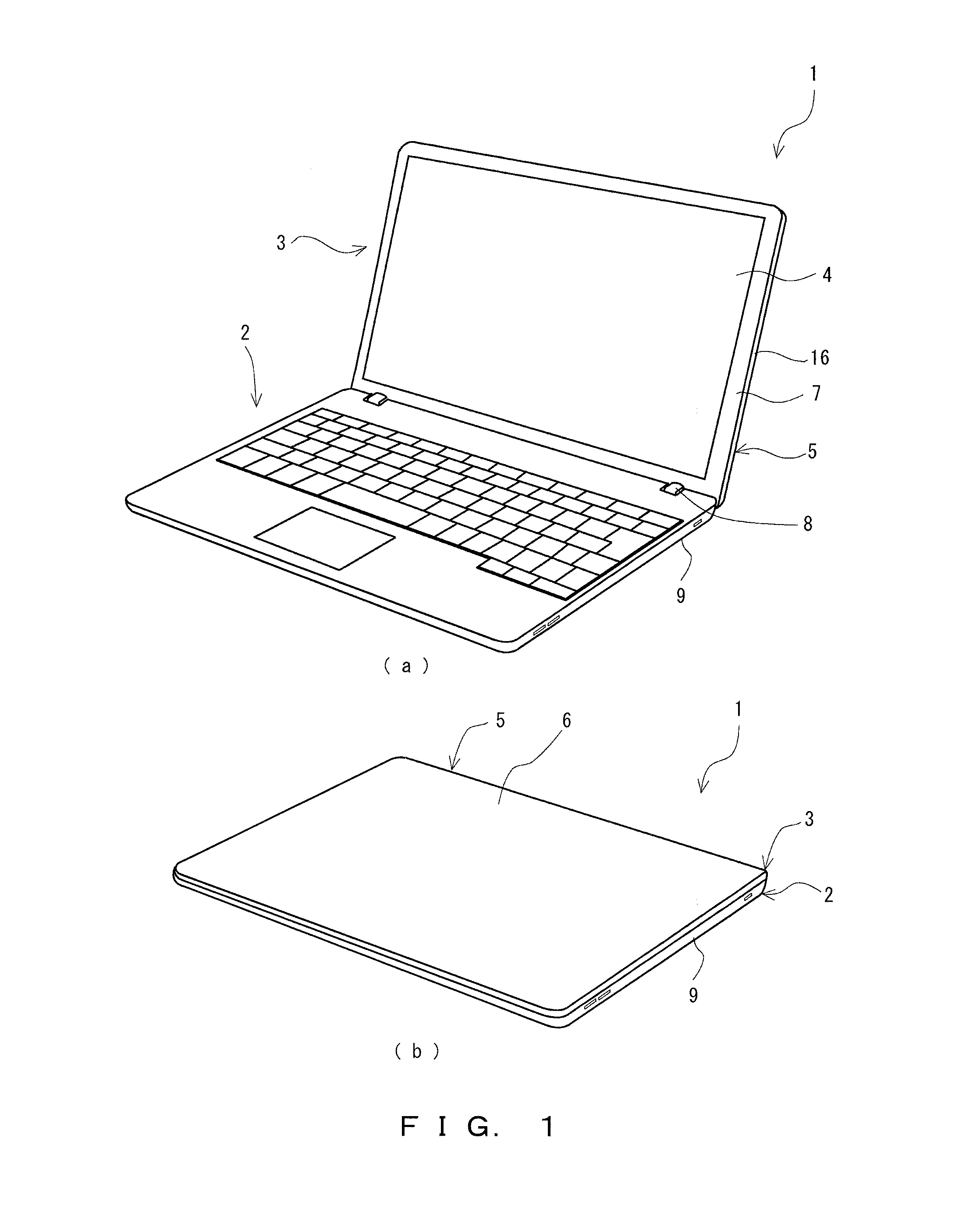
[0031]A portable terminal 1 shown in FIG. 1 includes an operation unit 2, and a liquid crystal display unit 3 rotatably (enabling to be opened / closed) attached to the operation unit 2. A housing of the portable terminal 1 (i.e., a casing that totally accommodates components of the portable terminal 1) has a thickness of no greater than 21 mm at the thickest part when the liquid crystal display unit 3 is closed, and therefore the portable terminal 1 is an ultrathin laptop computer (hereinafter, may be also referred to as “ultrathin computer 1”).

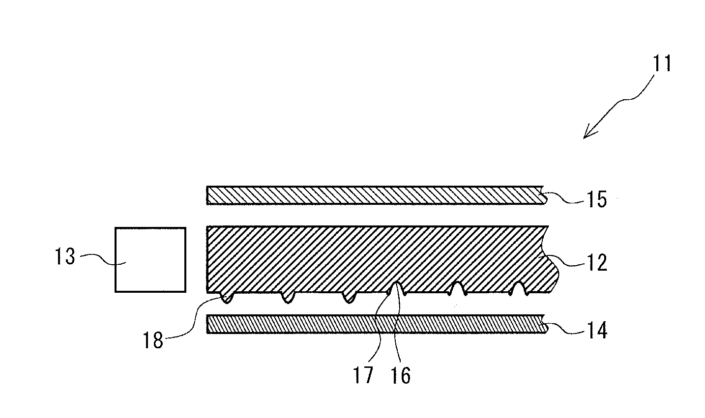
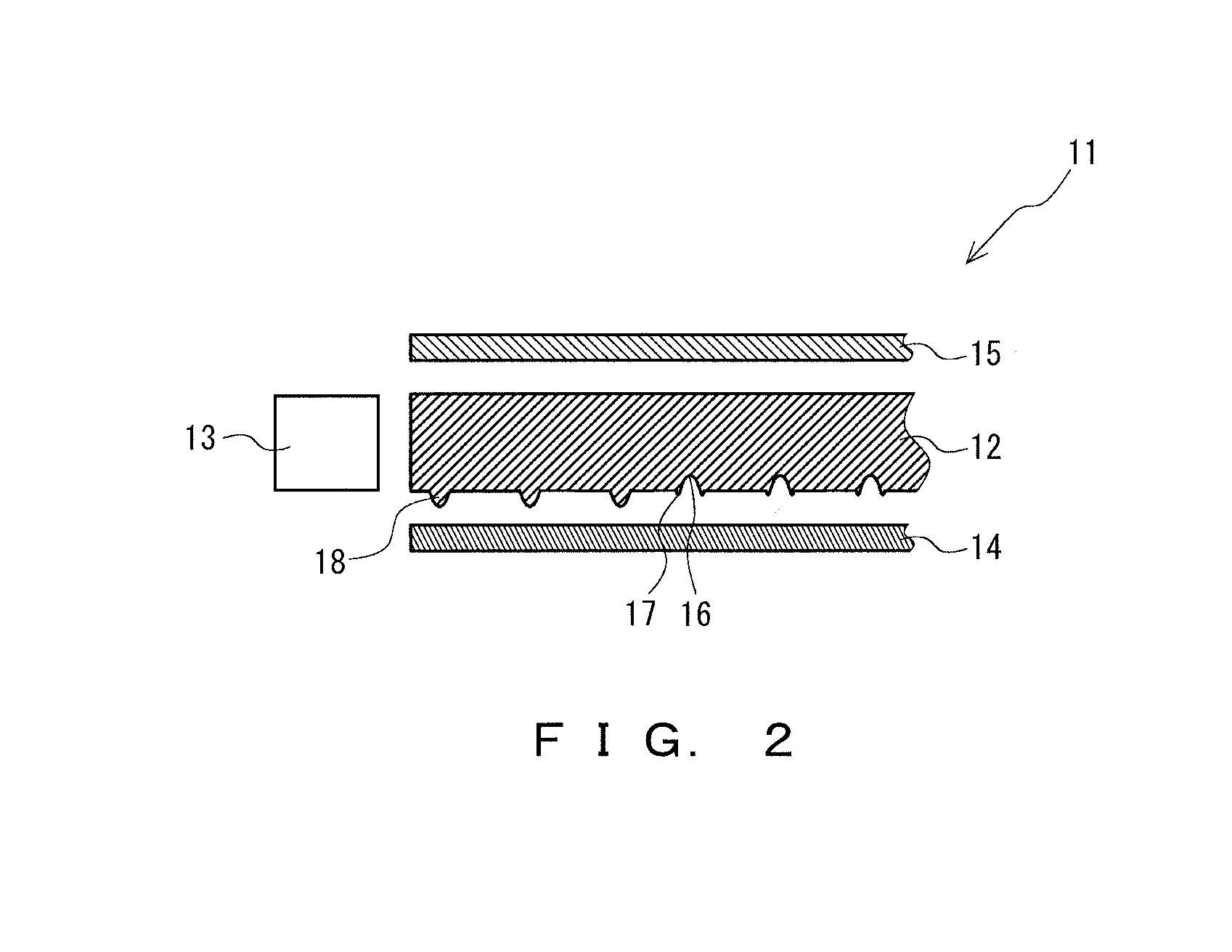
[0032]The liquid crystal display unit 3 of the ultrathin computer 1 includes a liquid crystal panel 4, and an edge-lit, ultrathin backlight unit that emits rays of light toward the liquid crystal panel 4 from the back face side. The liquid crystal panel 4 is held at the back face, the lateral face and a circumference of the front face by a casing for a liquid crystal display unit 5 of the housing. In this embodiment, the casin...


PUM

PropertyMeasurementUnit
thicknessaaaaaaaaaa
thicknessaaaaaaaaaa
heightaaaaaaaaaa

Abstract

An optical waveguide sheet for use in an edge-lit backlight unit is provided, that allows rays of light to enter the end face and emits the rays of light from the front face substantially uniformly. The optical waveguide sheet includes on the back side thereof: a sticking preventive means; and a plurality of recessed portions falling toward the front face side. The sticking preventive means: a plurality of annular raised portions each provided around each of the plurality of recessed portions and projecting toward the back face side; and a plurality of protruding portions provided scatteredly in a region which does not include the annular raised portions. The optical waveguide sheet is preferably for use as a light guide film having an average thickness of no less than 100 μm and no greater than 600 μm.

Description

FIELD OF THE INVENTION[0001]The present invention relates to an optical waveguide sheet, a backlight unit, and a portable terminal.BACKGROUND OF THE INVENTION[0002]Liquid crystal display devices in widespread use have been in a backlight system where light emission is executed by illuminating a liquid crystal layer from the rear face. In this system, a backlight unit such as edge-lit backlight unit or a direct-lit backlight unit is mounted on the underside of the liquid crystal layer. As shown in FIG. 7a, such an edge-lit backlight unit 110 generally includes a reflection sheet 115 disposed on the front face of a top plate 116, an optical waveguide sheet 111 disposed on the front face of the reflection sheet 115, an optical sheet 112 disposed on the front face of the optical waveguide sheet 111, and a light source 117 that emits rays of light toward the end face of the optical waveguide sheet 111 (see Japanese Unexamined Patent Application, Publication No. 2010-177130). In the edge-...

Claims


Application Information

Patent Timeline
Patent Type & Authority Applications(United States)
IPC IPC(8): F21V8/00G02F1/1335
CPCG02F1/1336G02B6/0036G02B6/0055G02B6/0058G02B6/0035G02B6/10G02F1/133524G02F1/133615
Inventor NAKASHIMA, HIRONORIHARADA, KENICHI
Owner KEIWA INCORPORATED
Why Eureka
Try Eureka