Zoom lens for projection and projection-type display apparatus

a technology of projection and display apparatus, applied in the field of zoom lens for projection and projection type display apparatus, can solve the problems of difficult reduction in the size of the lens, long total length, large magnification-side lens diameter, etc., and achieve the effect of reducing the size of the apparatus, reducing the diameter of the reduction-side lens, and appropriating back focus

Active Publication Date: 2015-08-20
FUJIFILM CORP
View PDF11 Cites 9 Cited by
  • Summary
  • Abstract
  • Description
  • Claims
  • Application Information

AI Technical Summary

Benefits of technology

[0055]The zoom lens for projection of the present invention adopts negative lead type configuration of lens groups. Further, fixed groups and movable groups are appropriately set, and the reduction side is non-telecentric. Especially, the configuration of the last lens group arranged closest to the reduction side is appropriately set. Therefore, the zoom lens is configurable to have a wide angle of view. Further, it is possible to secure an appropriate back focus, and to reduce the reduction-side lens diameter, thereby contributing to reduction in the size of the apparatus, at the same time. Further, the zoom lens for projection is easily configurable in such a manner that an F-number is kept almost constant during magnification change. It is possible to give excellent optical performance to the zoom lens for projection.

Problems solved by technology

However, since many lenses need to be combined together to achieve sufficient image formation performance, the total length becomes long, and a magnification-side lens diameter becomes large.
Therefore, reduction in the size of the lens is not easy.
Therefore, the zoom lenses have not satisfied a request for a zoom lens for projection that the brightness of a projection image in the same screen size is kept almost constant through the entire zoom range.

Method used


Image

  • Zoom lens for projection and projection-type display apparatus
  • Zoom lens for projection and projection-type display apparatus
  • Zoom lens for projection and projection-type display apparatus

Examples


example 1

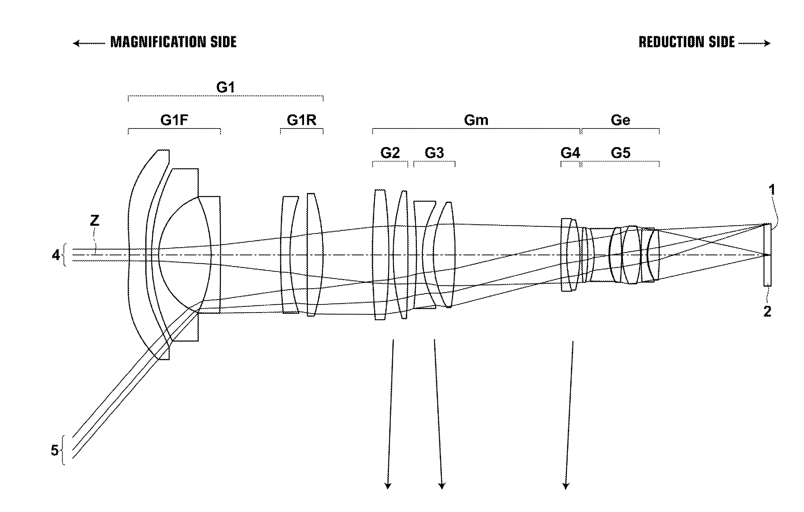
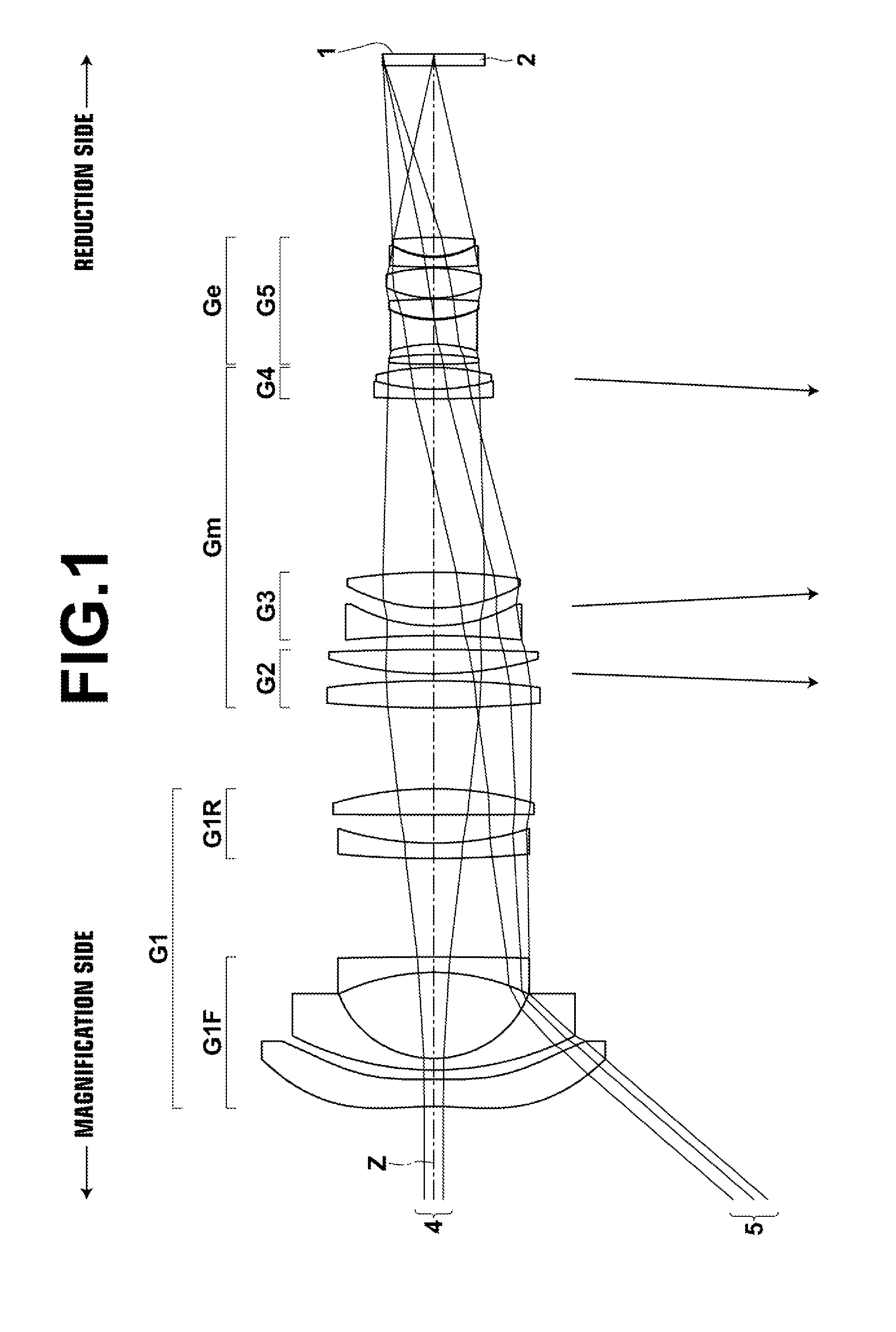
[0217]FIG. 4 is a diagram illustrating a cross section of the zoom lens for projection in Example 1 and paths of rays. In FIG. 4, the arrangement and configuration of each lens group at a wide-angle end, a middle focal length state and a telephoto end is illustrated in a top row, a middle row and a bottom row, respectively, to which signs W, M and T are given on the left side of FIG. 4. Further, in FIG. 4, axial rays 4, rays 5 at a maximum image height, a parallel-flat-plate-shaped optical member 2, which is assumed to be various filters, a cover glass or the like, and an image display surface 1 of a light valve located on a reduction-side surface of the optical member 2 are also illustrated. Further, arrows schematically indicating the directions of movement of each lens group when magnification is changed from a wide-angle end to a middle focal length state, and from the middle focal length state to a telephoto end are also illustrated between the top row and the middle row, and b...

example 2

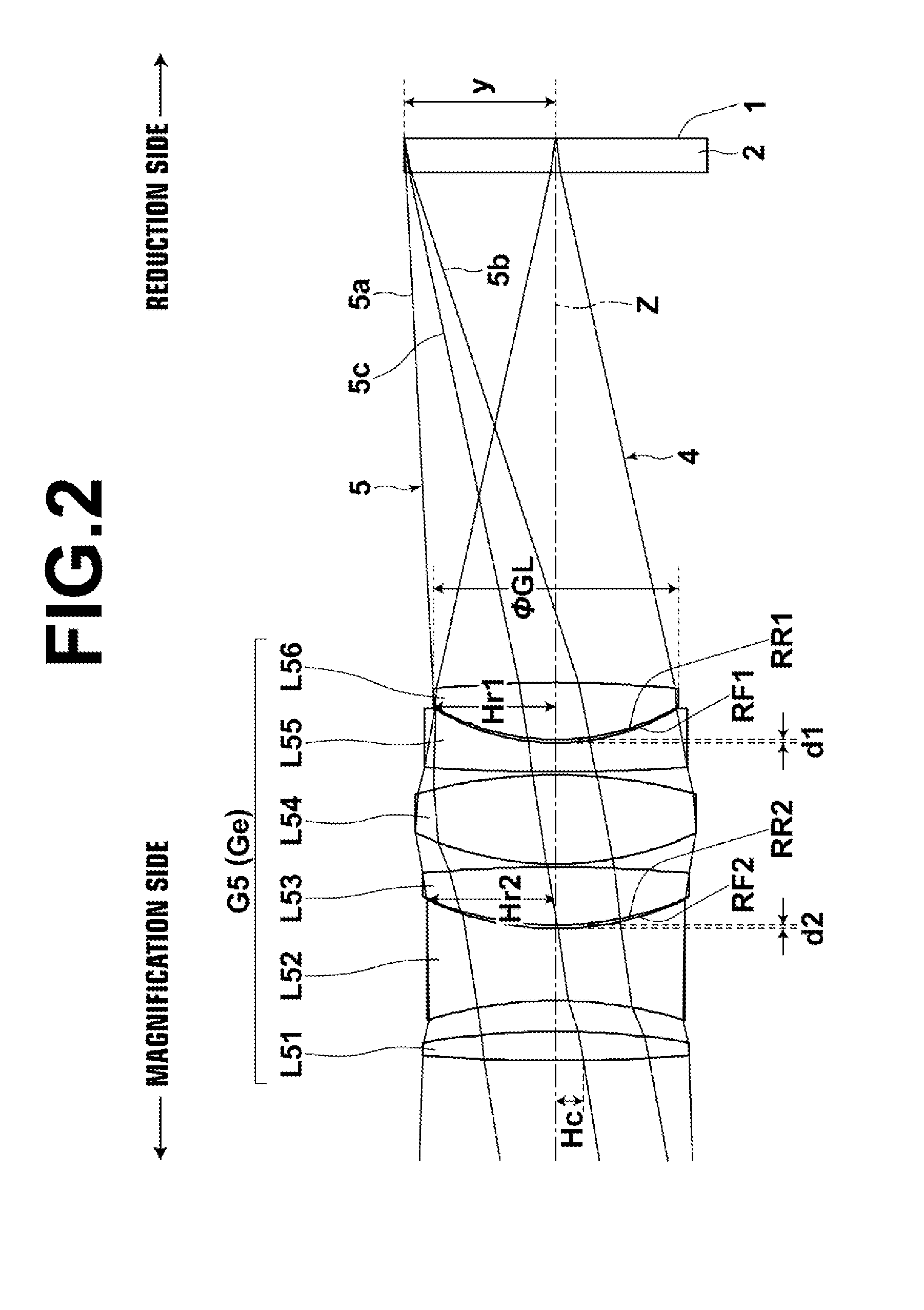
[0237]FIG. 5 is a diagram illustrating a cross section of the zoom lens for projection in Example 2 and paths of rays. In the zoom lens for projection of Example 2, the group configuration, the schematic configuration of each lens group, and a focusing method are almost similar to the zoom lens for projection in Example 1. The zoom lens for projection in Example 2 differs from Example 1 in that fifth lens group G5 consists of seven lenses of L51 through L57. Table 4, Table 5 and Table 6 show basic lens data of the zoom lens for projection in Example 2, aspherical coefficients, and specification for d-line and values of variable surface distances, respectively. FIG. 20, Sections A through L and FIG. 21, Sections A through L are aberration diagrams of the zoom lens for projection in Example 2. In Example 2, a reference projection distance is 119.17, and a closest projection distance is 58.61.

TABLE 4SiRiDiNdjνdj*1−6.22850.61051.4910057.58*2−36.58840.334135.81970.26171.6385455.3842.3080...

example 3

[0238]FIG. 6 is a diagram illustrating a cross section of the zoom lens for projection in Example 3 and paths of rays. In the zoom lens for projection of Example 3, the group configuration, the schematic configuration of each lens group, and a focusing method are almost similar to the zoom lens for projection in Example 1. Table 7, Table 8 and Table 9 show basic lens data of the zoom lens for projection in Example 3, aspherical coefficients, and specification for d-line and values of variable surface distances, respectively. FIG. 22, Sections A through L and FIG. 23, Sections A through L are aberration diagrams of the zoom lens for projection in Example 3. In Example 3, a reference projection distance is 119.12, and a closest projection distance is 58.59.

TABLE 7SiRiDiNdjνdj*1−6.22590.61031.4910057.58*2−36.57290.143235.68200.26151.6385455.3842.49752.03235−7.95380.31091.7725049.6065.4817DD[6] 754.63000.34871.6229958.1688.6925DD[8] 9−27.96240.55281.5163364.1410−7.1216DD[10]1116.86860.6...


PUM


Abstract

A zoom lens for projection consists of a negative first lens group, which is fixed during magnification change, a middle group, which includes plural lens groups that move during magnification change, and a positive last lens group, which is fixed during magnification change, in this order from a magnification side. A reduction side is non-telecentric. Both of a lens group closest to the magnification side and a lens group closest to the reduction side in the middle group have positive refractive power, and move from the reduction side toward the magnification side during magnification change from a wide-angle end to a telephoto end. The last lens group includes at least two positive lenses and at least two negative lenses. A positive lens is arranged closest to the reduction side in the last lens group. A predetermined conditional expression about a focal length of the last lens group is satisfied.

Description

CROSS-REFERENCE TO RELATED APPLICATIONS[0001]This application is a Continuation of PCT International Application No. PCT / JP2013 / 006455 filed on Oct. 31, 2013, which claims priority under 35 U.S.C. §119(a) to Japanese Patent Application No. 2012-251924, filed on Nov. 16, 2012. Each of the above applications is hereby expressly incorporated by reference, in its entirety, into the present application.BACKGROUND OF THE INVENTION[0002]1. Field of the Invention[0003]The present invention relates to a zoom lens for projection and a projection-type display apparatus. For example, the present invention relates to a zoom lens for projection appropriate to magnify and project an original image formed by a light valve or valves onto a screen and a projection-type display apparatus using the zoom lens for projection.[0004]2. Description of the Related Art[0005]Conventionally, projection-type display apparatuses that magnify and project images displayed on light valves, such as a liquid crystal d...

Claims


Application Information

Patent Timeline
Patent Type & Authority Applications(United States)
IPC IPC(8): G02B13/16G02B15/177G02B13/00
CPCG02B13/16G02B13/0045G02B15/177G02B13/009G02B13/006G02B13/18G02B15/167G02B15/20G02B15/143107G02B9/34G02B9/60G02B15/00
Inventor NAGAHARA, AKIKO
Owner FUJIFILM CORP
Why Eureka
Try Eureka