
Light source control module, backlight module and driving method thereof

a technology of light source control module and backlight module, which is applied in the field of display technology, can solve the problems of poor performance, insufficient color amount of existing display device, and lowered color saturation, and achieve the effects of lowering color saturation, sufficient color amount, and poor performan

Active Publication Date: 2015-08-20
BOE TECH GRP CO LTD +1
View PDF1 Cites 11 Cited by
  • Summary
  • Abstract
  • Description
  • Claims
  • Application Information

AI Technical Summary

Benefits of technology

The present invention provides a solution to existing display devices that have insufficient color amount, poor performance and lowered color saturation. The invention provides a light source control module, a backlight module and a driving method that render sufficient color amount, improved performance and better color saturation.

Problems solved by technology

Technical problems to be solved by the present invention include that the existing display device has insufficient color amount, poor performance and lowered color saturation.

Method used


Image

  • Light source control module, backlight module and driving method thereof
  • Light source control module, backlight module and driving method thereof
  • Light source control module, backlight module and driving method thereof

Examples


embodiment 1

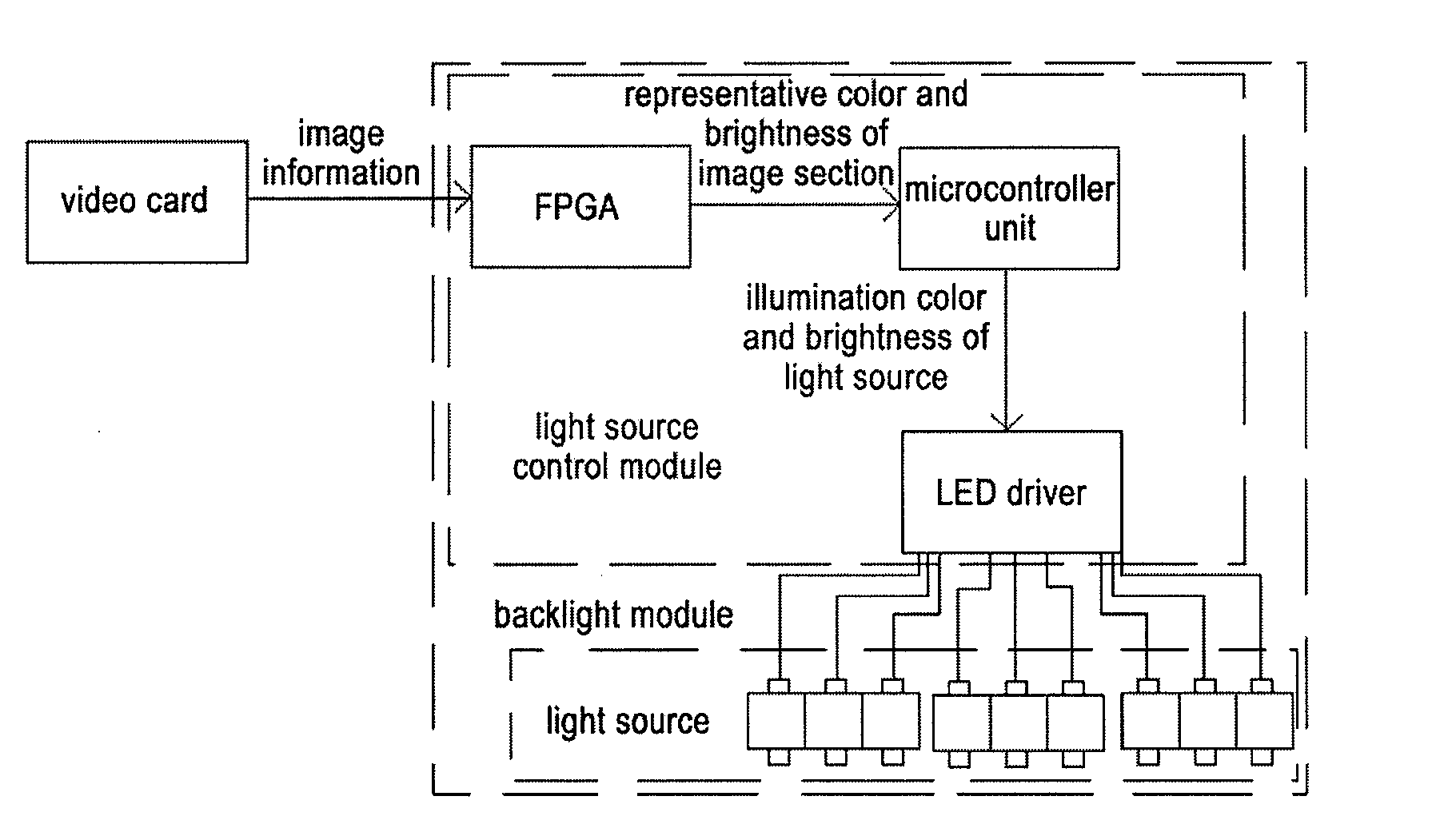
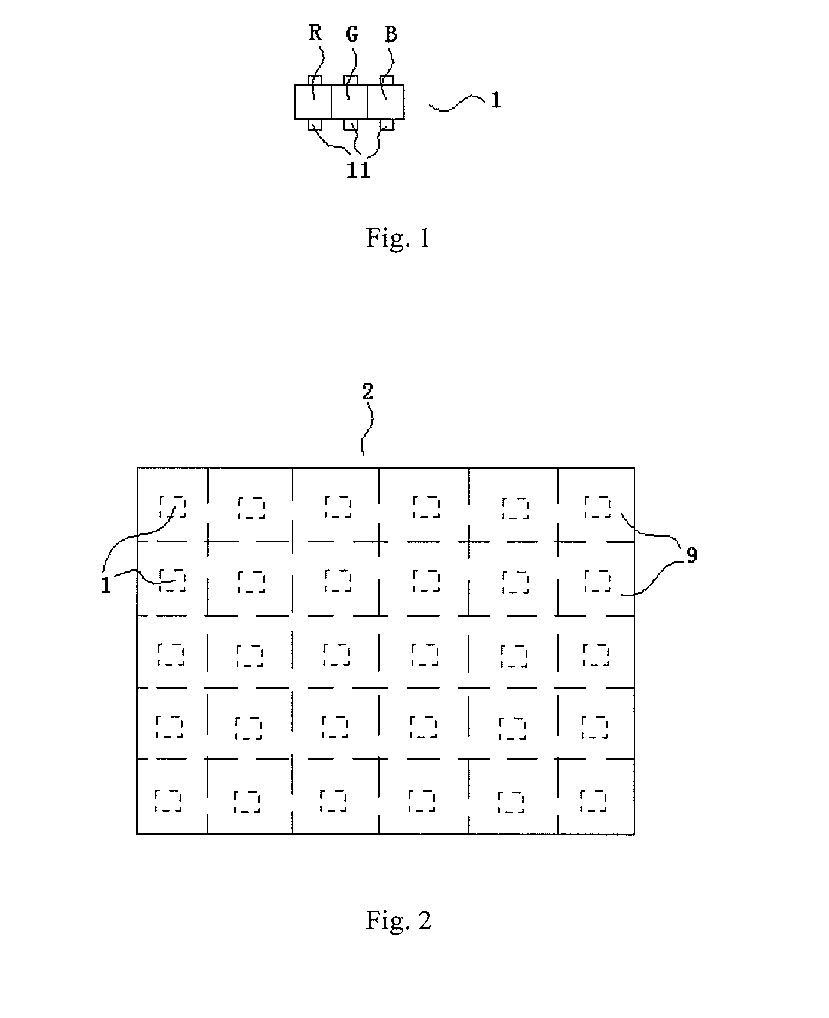
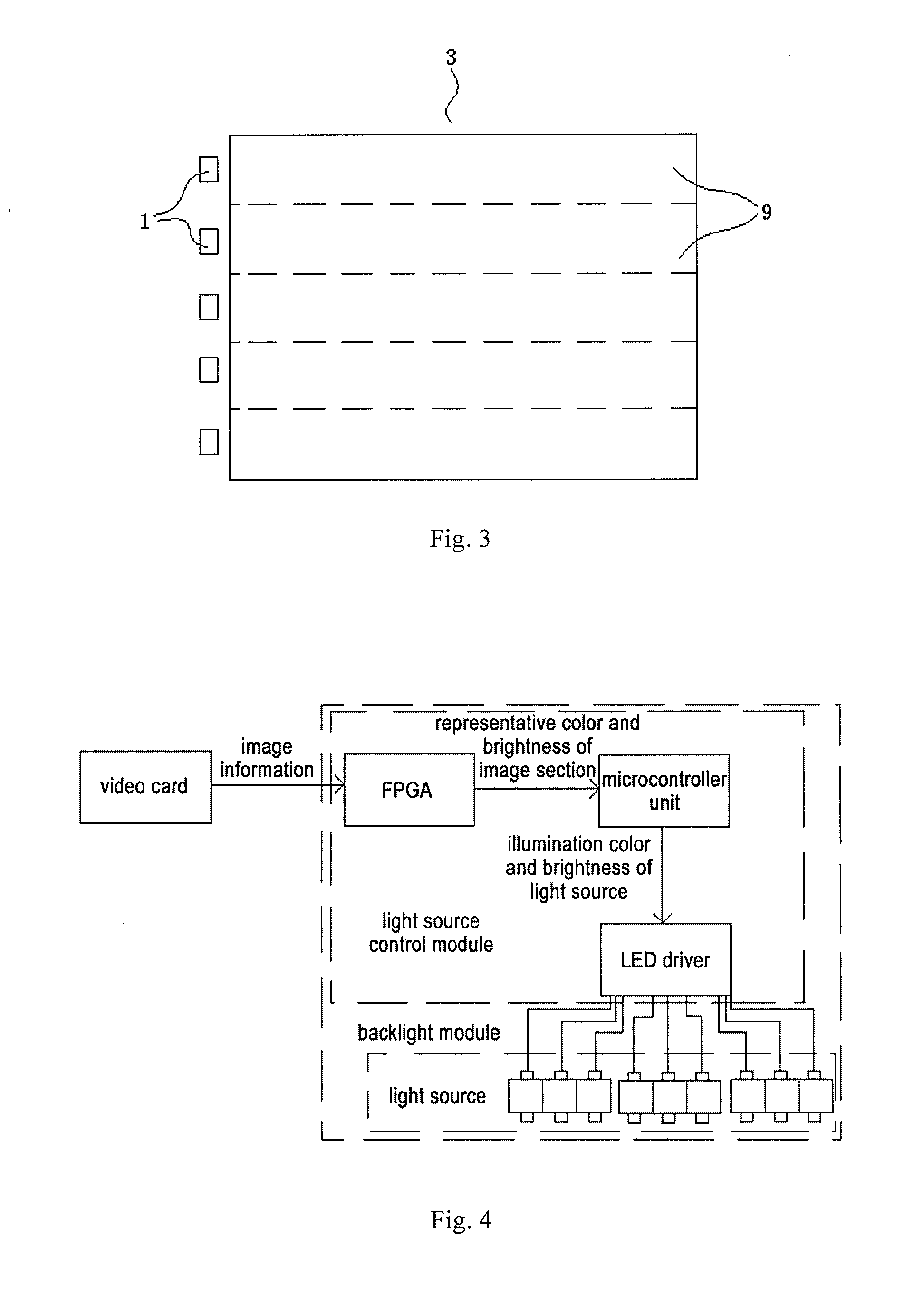
[0030]As shown in FIGS. 1-5, the present embodiment provided a light source control module, a backlight module in which the light source control module is applied, and a driving method of the backlight module.

[0031]The light source control module is used for controlling illumination colors and / or brightness of each light source in the backlight module separately according to image information.

[0032]That is, the light source control module is used for controlling the light sources of the backlight module in the LCD device, and is different from existing light source control module in that, the respective light sources are controlled in an independent manner according to the image to be displayed. The color and / or brightness of light output from different positions on the backlight module is in conformity with the contents in respective areas of the image to be displayed, such that the colors of the image are improved, the color amount is increased, color performance and color saturat...

embodiment 2

[0082]The present embodiment provides a display device comprising above backlight module. The display device also comprise other known components such as display panel, case and power supply, the detailed description there of is omitted here.

[0083]The backlight module of the present invention is applicable to any display device using backlight, such as LCD panel, E-paper, mobile phone, tablet PC, TV set, monitor, laptop computer, digital photo frame, navigator, MEMS system and like product or component having a display function.


PUM


Abstract

The present invention provides a light source control module, a backlight module and driving method thereof which can overcome the problems of insufficient color amount, poor performance and lowered color saturation. A light source control module of the present invention is used for separately controlling illumination colors and / or brightness of each light source in the backlight module according to image information. The driving method of the backlight module comprises: calculating representative color and / or brightness of each image section based on image information, wherein each image section corresponds to a light output area on the output surface of the backlight module, each light output area is illuminated by one light source in the backlight module; adjusting the illumination colors and / or brightness of each light source such that the color and / or brightness of each light output area is in conformity with the representative color and / or brightness of corresponding image section.

Description

FIELD OF THE INVENTION[0001]The invention relates to the field of display technology, in particular to a light source control module, a backlight module and driving method of the backlight module.BACKGROUND OF THE INVENTION[0002]The liquid crystal display device has advantageous such as low power consumption, reduced thickness, no radiation and long lifetime, therefore the application of the liquid crystal display device becomes more and more wide. Typically, a liquid crystal display device mainly include a display panel and a backlight module, wherein the backlight module is used for emitting uniform white light to the display panel, and each pixel of the display panel filters the light from the backlight module to adjust the light transmittance at each pixel, and color filters for different colors are disposed at each pixel, such that light transmitted through each pixel has different colors and together forms a color display.[0003]However, in the liquid crystal display device, th...

Claims


Application Information

Patent Timeline
IPC IPC(8): G09G3/34G02F1/1335F21V9/10F21V9/40
CPCG09G2320/0646F21Y2115/10F21Y2113/13G02F1/1336G09G3/3413G09G3/3426G09G2320/062G09G2360/16
Inventor MENG, ZHIMINGYOON, DAEKEUNHU, WEIHAOHE, ZONGZEWANG, JIANMING
Owner BOE TECH GRP CO LTD
Learn More