Electromagnetic Shield Termination Device

a technology of electromagnetic shield and termination device, which is applied in the direction of cable termination, cable junction, earth/grounding circuit, etc., can solve the problems of difficult and time-consuming assembly and disassembly of backshell assemblies, and conventional electromagnetic termination connectors do not allow interruption or termination of electrical wiring systems

Active Publication Date: 2015-08-20
LEAR CORP
View PDF10 Cites 11 Cited by
  • Summary
  • Abstract
  • Description
  • Claims
  • Application Information

AI Technical Summary

Problems solved by technology

One common method of terminating and grounding such electromagnetic shields is a backshell assembly with a compression ring, but such backshell assemblies are difficult and time-consuming to assemble and disassemble.
Also, conventional electromagnetic termination connectors do not allow for interruption or termination of electrical wiring systems between devices in locations where an electromagnetic shield is not necessary, i.e., where EMI is not present, and therefore where EMC is not required.

Method used


Image

  • Electromagnetic Shield Termination Device
  • Electromagnetic Shield Termination Device
  • Electromagnetic Shield Termination Device

Examples


first embodiment

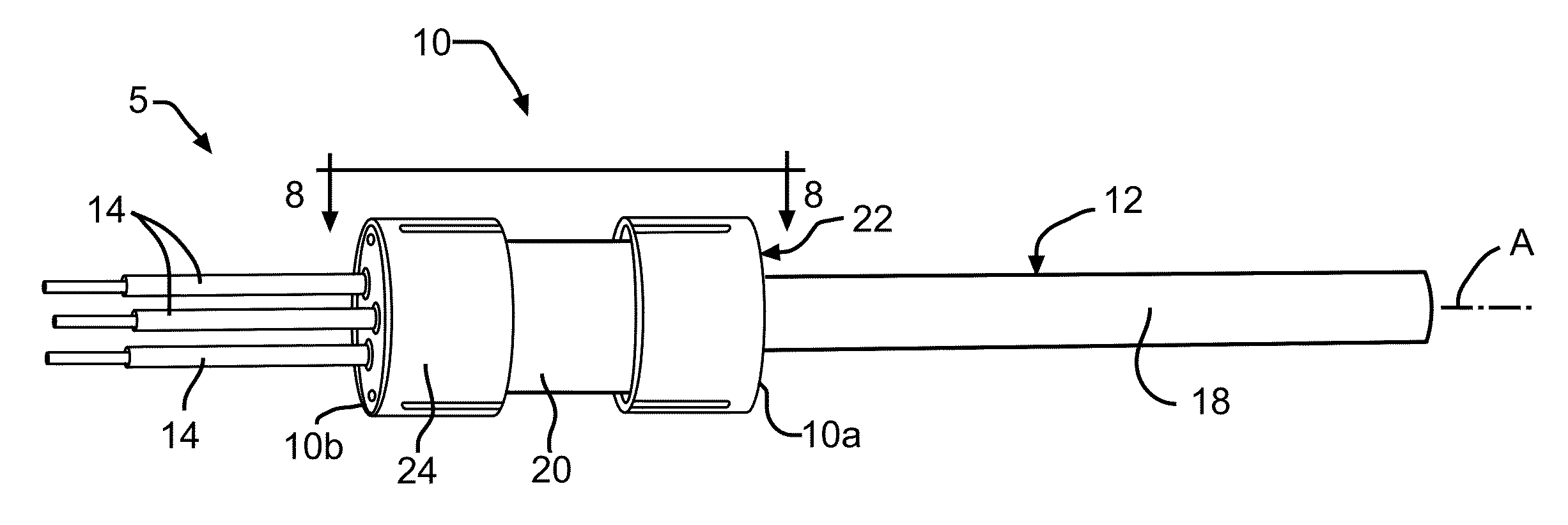
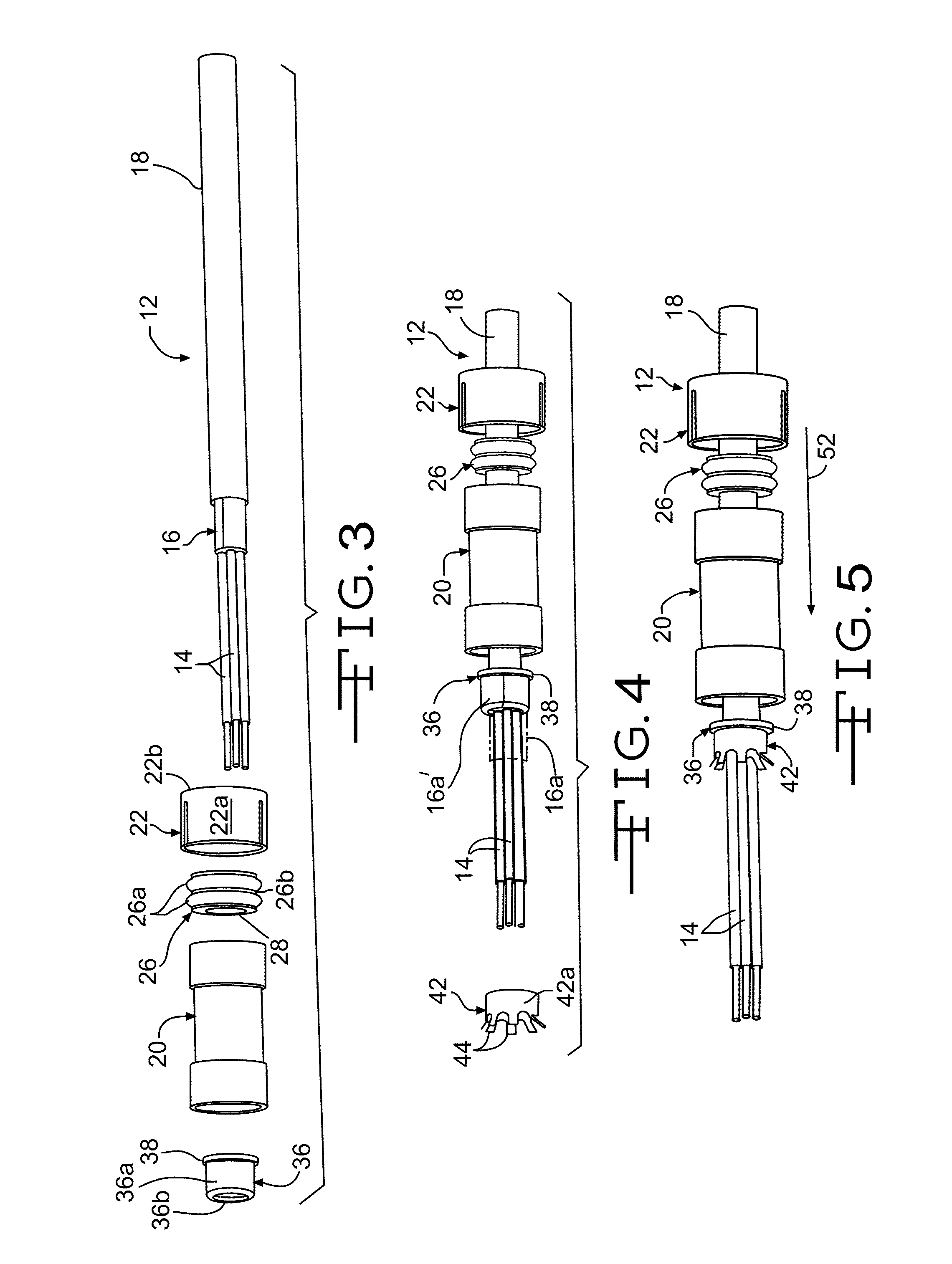
[0027]Referring now to the drawings, FIGS. 1 through 9 illustrate portions of an electromagnetic shield termination assembly 5 having an improved termination device 10 for an electromagnetic shield. In FIG. 1, the improved termination device 10 is shown assembled on a multi-core wire assembly 12. The structure and function of both the termination device 10 and the multi-core wire assembly 12 will be described in detail below.

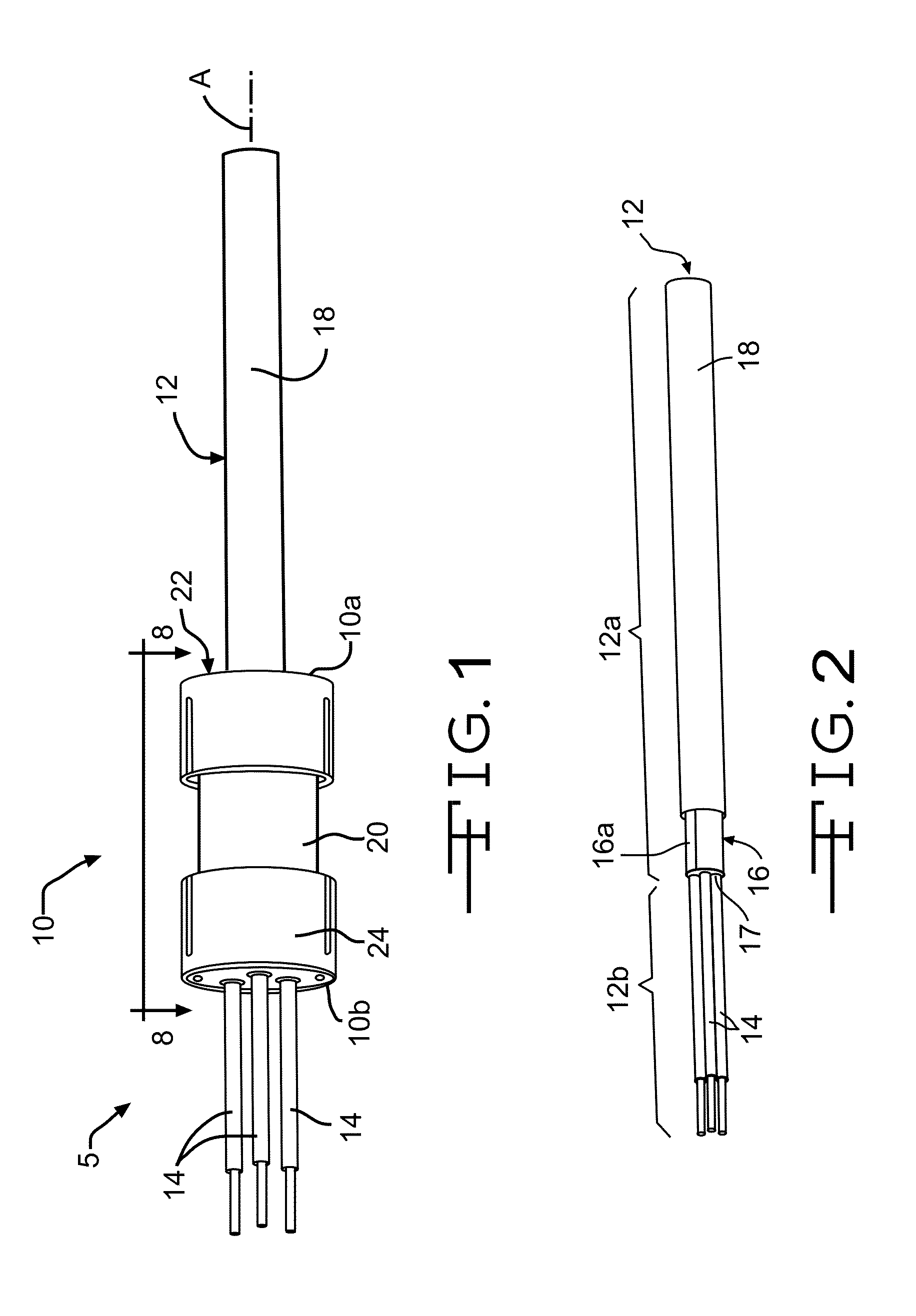
[0028]The multi-core wire assembly 12, best shown in FIG. 2, is conventional in the art and includes a plurality of insulated electrically conductive wires 14 defining a wire axis A. The illustrated multi-core wire assembly 12 includes three insulated electrically conductive wires 14. Alternatively, the multi-core wire assembly 12 may include any desired number of insulated electrically conductive wires 14. As described in detail below, the improved termination device 10 may also be adapted for use with a single-core wire assembly.

[0029]As best shown in FIG. 2, ...

second embodiment

[0052]a ground strap is shown at 58 in FIG. 11. In the exemplary embodiment illustrated in FIG. 11, the ground strap 58 is an electrically conductive wire that is electrically connected to the housing 20, such as by welding, and further attached to the metallic portion 54a of the vehicle 54, such as shown in FIG. 10. Like the clamp 56, the wire 58 may be attached to any suitable ground location in the vehicle 54 by any desired means, such as with a fastener (not shown), a conventional electrical wire connector (not shown), or by welding. Alternatively, the wire 58 may be attached to any desired metallic portion of the vehicle 54. The wire 58 acts to reduce undesirable electrical noise via the ground to which it is attached.

[0053]A second embodiment of the termination device is shown at 60 in FIG. 12. The termination device 60 is identical to the termination device 10, but includes a ferrite bead 62 on a ground wire 64 of the plurality of electrically conductive wires 14. The ferrite...

third embodiment

[0054]the termination device is shown at 70 in FIG. 13. The termination device 70 is similar to the termination device 10, but includes an electrically conductive first seal retainer 72 in lieu of the first seal retainer 22. An electrically conductive wire 74 is electrically connected to the retainer 72 and to the metallic portion 54a of the vehicle 54 by any desired means, such as with a conventional electrical wire connector 76, a fastener (not shown), or by welding. As described above and shown in FIG. 8, the external current can flow through the folded portion 16a′ of the wire shield 16, the body 42a and the engaging arms 44 of the outer ferrule 42, and the housing 20. The electrically conductive first seal retainer 72 then allows the external current to additionally flow from the housing 20 through the retainer 72 and the wire 74 to a ground, such as the metallic portion 54a of the vehicle 54, shown in FIG. 10. Alternatively, the wire 74 may be attached to any desired metallic ...


PUM


Abstract

An electromagnetic shield termination assembly includes a wire assembly having an electrically conductive wire. An electromagnetic shield extends coaxially with the electrically conductive wire and covers at least a portion of a circumference of the electrically conductive wire, the electromagnetic shield and the electrically conductive wire covered thereby defining a shielded portion of the wire assembly. A non-shielded portion of the wire assembly extends outward of a terminal end of the electromagnetic shield. A termination device has an electrically conductive housing mounted to the wire assembly about the terminal end of the electromagnetic shield such that a portion of the housing engages a portion of the electromagnetic shield, and wherein the housing provides a flow path for an electrical current flowing in the electromagnetic shield.

Description

CROSS REFERENCE TO RELATED APPLICATIONS[0001]This application claims the benefit of U.S. Provisional Application No. 61 / 940,604 filed Feb. 17, 2014, the disclosure of which is incorporated herein by reference.BACKGROUND OF THE INVENTION[0002]This invention relates in general to a device for terminating an electromagnetic shield on a wire. In particular, this invention relates to an improved structure for such a device that terminates an electromagnetic shield between terminal ends of shielded single and multi-core wire assemblies, and at a point where a shielded portion of the wire assembly transitions to a non-shielded portion of the wire assembly.[0003]With the proliferation in use of electronics and electronic equipment, it has become increasingly important to protect sensitive electronic equipment from the negative effects of electromagnetic interference (EMI). One way to protect electronic equipment is to provide an electromagnetic shield over wires that are connected to the eq...

Claims


Application Information

Patent Timeline
Patent Type & Authority Applications(United States)
IPC IPC(8): H05K9/00H02G15/02H02G15/04
CPCH05K9/0098H05K9/0064H02G15/025H02G15/04H02G15/046
Inventor NATTER, BRANTLEYDESCOMBES, ERICTARMOOM, EHAB
Owner LEAR CORP
Why Eureka
Try Eureka