

Wire electric discharge machine having corner shape compensation function
a technology of corner shape compensation and electric discharge machine, which is applied in the direction of electric programme control, program control, instruments, etc., can solve the problems of unable to always obtain the desired shape, and inevitably reducing the shape accuracy of the circular-arc portion. achieve the effect of improving the shape accuracy of the circular-arc portion
- Summary
- Abstract
- Description
- Claims
- Application Information
AI Technical Summary
Benefits of technology
Problems solved by technology
Method used
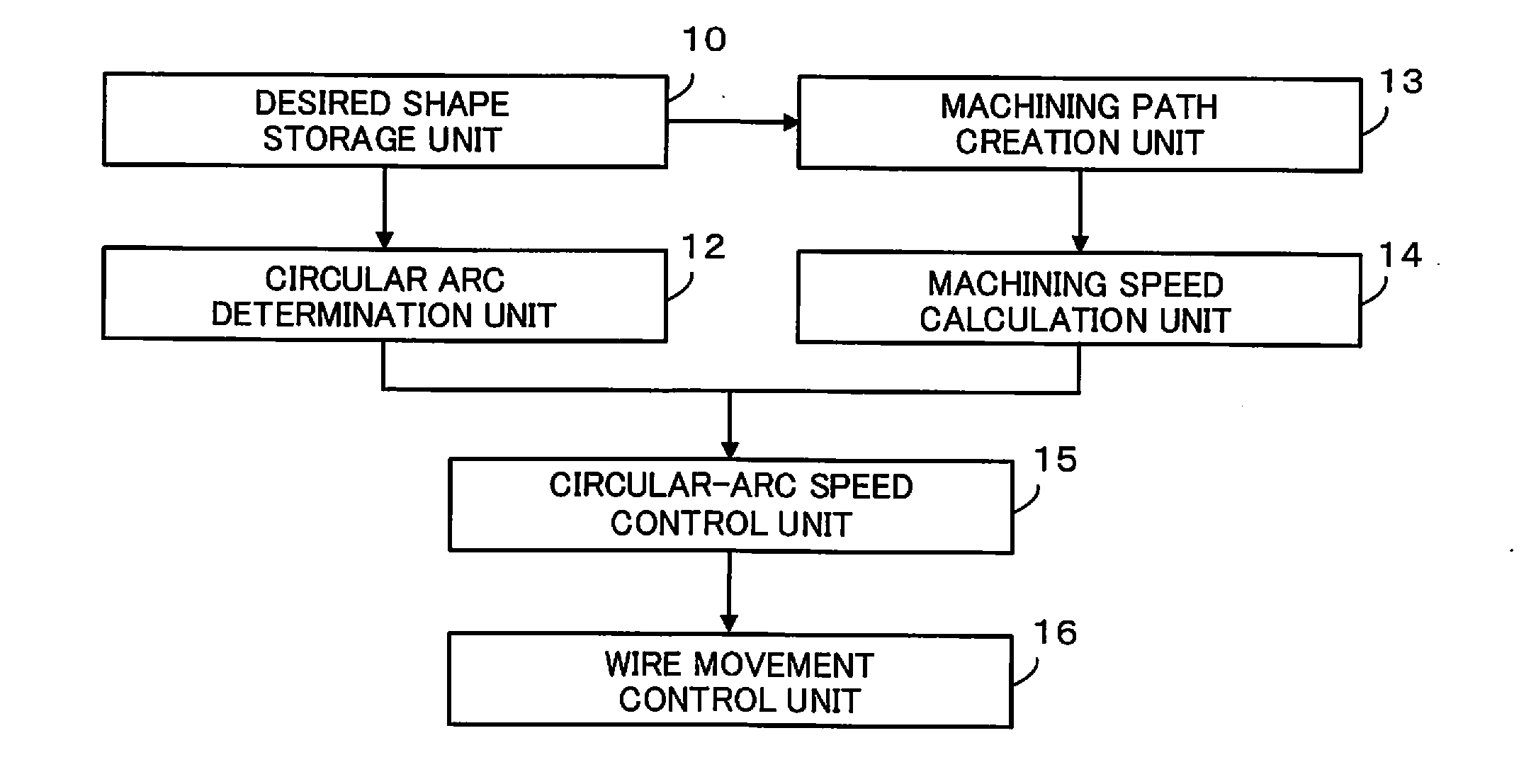
Image

Examples
embodiment 1
[0074]In order to secure the shape accuracy of the circular-arc portion, as described above, the discharge densities of the circular-arc and straight portions of the desired shape should be made uniform. The discharge densities can be made uniform by controlling the command speed at the circular-arc portion of the machining path. The following is a description of an example of the method for controlling the command speed.
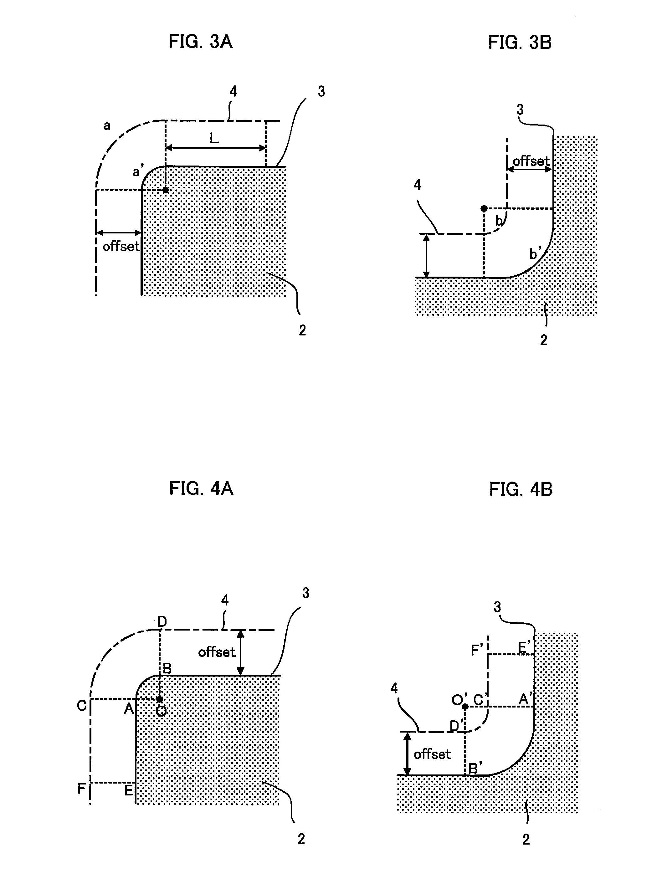
[0075](1) The case of the convex circular arc of FIG. 4A will be described by way of example. If a discharge density ET per unit time is constant and if average machining speeds in the sections AB and AE of the desired shape 3 are vAB and vAE, respectively, a discharge per unit distance in the sections AB and AE of the desired shape 3 can be obtained from equations (4) as follows:
EABa=ET×vAB
EAEa=ET×vAE (4)
[0076]In order to make the discharge densities per unit distance in the circular-arc and straight portions of the desired shape 3 uniform by equation (4), the av...
embodiment 2
[0085]In the case of a circular-arc portion, as described in connection with Embodiment 1, if the command speed on the machining path is reflected on its corresponding desired shape, depending on the difference in arc length between the desired shape and the machining path, a difference is generated. In the case of a convex circular arc, the arc length of the desired shape is shorter than that on the machining path, so that the machining speed at the desired shape is lower than that on the actual machining path. In the case of a concave circular arc, the arc length of the desired shape is longer than that on the machining path, so that the machining speed at the desired shape is higher than that on the actual machining path.
[0086]In the case where the machining speed is calculated according to the machining voltage, discharge pulse, etc., the machining speed is controlled so that the discharge densities in the straight and circular-arc portions on the machining path are uniform (or ...
embodiment 3
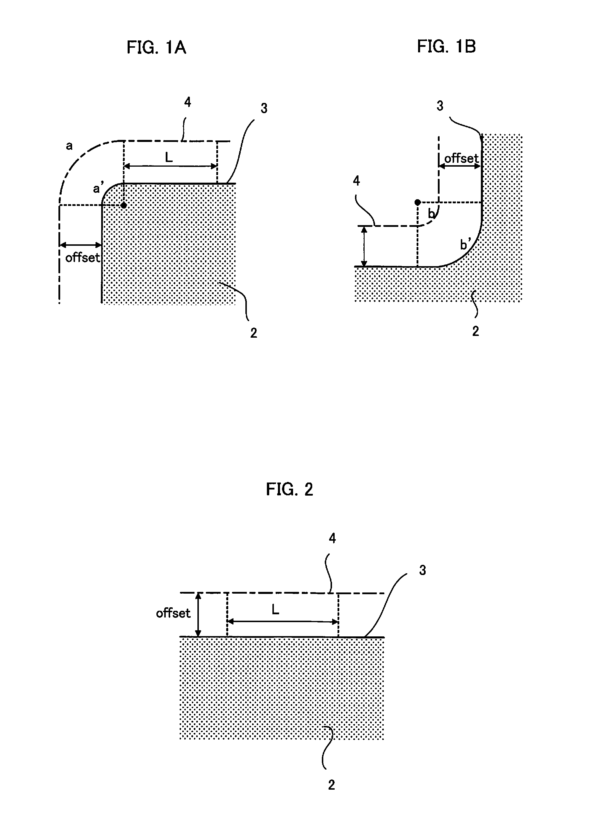
[0096]In wire electric discharge machining, as mentioned before, a desired shape is usually created in advance with reference to a drawing. A movement path of the center of a wire, based on this desired shape in consideration of the discharge gap, wire diameter, etc., is referred to as “machining path”. The discharge gap, wire diameter, etc., as added conditions, are collectively referred to as “offset”.
[0097]As described in connection with Embodiments 1 and 2, the command speed for the circular-arc portion can easily be obtained taking advantage of the relationship of arc length between a desired shape and the corresponding machining path. FIG. 9 is a diagram showing a relationship between a desired shape in a convex circular-arc portion and the corresponding machining path. As seen from FIG. 9, the desired shape and the machining path are concentric with each other at the circular-arc portion.
[0098]The proportional relationship in length between circular arcs of concentric circles...
PUM
| Property | Measurement | Unit |
|---|---|---|
| Length | aaaaa | aaaaa |
| Thickness | aaaaa | aaaaa |
| Speed | aaaaa | aaaaa |
Abstract
Description
Claims
Application Information