Rear-mounted aerodynamic structures for cargo bodies

a cargo body and rear-mounted technology, applied in the field of aerodynamic structures, can solve the problems of large rear aerodynamic structures, inability to provide aerodynamic structures that integrate with the structure and function of the rear cargo doors of the truck, and inability to meet the requirements of cargo body rolling doors, etc., to avoid damage to the upper panel and improve the contact angle in collision

Active Publication Date: 2015-08-27
STEMCO PROD INC
View PDF1 Cites 13 Cited by
  • Summary
  • Abstract
  • Description
  • Claims
  • Application Information

AI Technical Summary

Benefits of technology

[0010]A three- or four-sided aerodynamic structure improves the airflow associated with the movement of a cargo body, such as a body of a truck or trailer. The three-sided aerodynamic structure includes an upper panel and a side panel disposed on each of a pair of doors of the cargo body that, when in the deployed position, define a three-sided aerodynamic structure at the rear of the cargo body. The four-sided aerodynamic structure further includes a pair of bottom panels for defining a four-sided aerodynamic structure when in the deployed position. A swingarm can also be incorporated with the three- or four-sided aerodynamic structure, operatively connecting the upper panel, side panel and the cargo body door, so that the panels move in a coordinated manner.
[0011]In an illustrative embodiment the top or upper panel can comprise a lightweight panel that incorporates an actuator (e.g. a gas spring) to bias the side panel open. According to another illustrative embodiment, the upper panel can be operatively connected to the side panel via a linkage, which connects the movement of the side panel to the top panel so that opening the side panel forces the top panel open. Similarly, collapsing the lateral panel, through the linkage, pulls down on the top panel to assist with closing the overall aerodynamic structure.
[0012]In another embodiment, automatic opening or deployment of the doors, under bias of the actuator, can be provided using a top-mounted or side-mounted pivoting tab structure, that causes a latch cable or other switching device to be released when the tab pivots in response to drag / wind resistance at a predetermined travel speed. This allows for non-deployment at low speeds (e.g. city driving, where the extra length could be problematic), while higher (e.g., highway) speeds cause deployment of the aerodynamic structure. The tab is operatively connected by, illustratively, a cable assembly that is secured to a latch or an aerodynamic panel. When the actuator biases the panel outwardly, it tensions the cable, causing the tab to pivot back into a low-drag configuration.
[0015]In illustrative embodiments, an upper panel crash bar can be provided that is secured to the upper panel that improves contact angle in collision and assists folding of the top panel to avoid damage to the upper panel. A plurality of bi-directional spring-loaded hinges can also be provided that are biased to hold the upper panel and the side panel in the deployed position, but permit inward-folding of the upper panel and the side panel when the door of the cargo body is opened and the side panel contacts a side of the trailer and pushes the side panel inward.

Problems solved by technology

The flat, projecting front face of a cargo body is a substantial source of drag, above the cab roof.
To improve the aerodynamics of a truck or trailer cargo body by reducing drag, several solutions have been provided that focus on trucks having swinging doors, which are not always readily applicable to cargo bodies having rolling doors.
Most attempts to provide aerodynamic structures that integrate with the structure and function of the rear cargo doors of a truck have been unsuccessful and / or impractical to use and operate.
Such rear aerodynamic structures are typically large and difficult to remove from the rear so as to access the cargo doors when needed.
However, aerodynamic structures that swing upwardly require substantial strength or force to be moved away from the doors, and also require substantial height clearance above an already tall cargo body.
While this requires less force to move, it also requires substantial side clearance—which is generally absent from a closely packed, multi-truck loading dock.
In such an environment, side-projecting or top-projecting fairings would invariably interfere with operations at the loading dock.
Another challenge to providing a rear aerodynamic structure is the prompting of a user to deploy the aerodynamic structure at the appropriate time.
In particular, if this is performed too late, it may not have the desired effectiveness on improving fuel efficiency and aerodynamic drag, and if performed at lesser speeds, the aerodynamic structure may be unnecessary.

Method used


Image

  • Rear-mounted aerodynamic structures for cargo bodies
  • Rear-mounted aerodynamic structures for cargo bodies
  • Rear-mounted aerodynamic structures for cargo bodies

Examples


Embodiment Construction

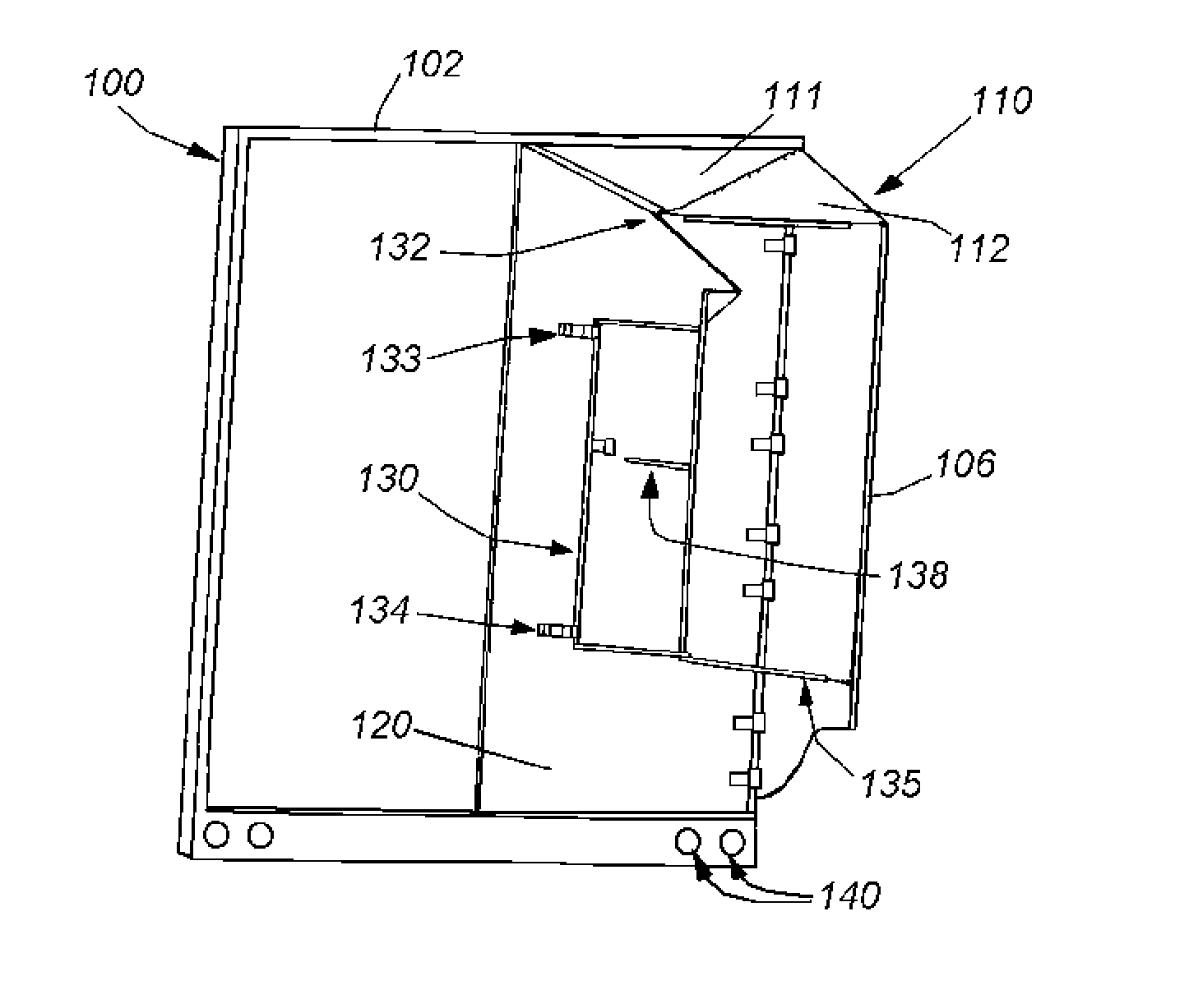
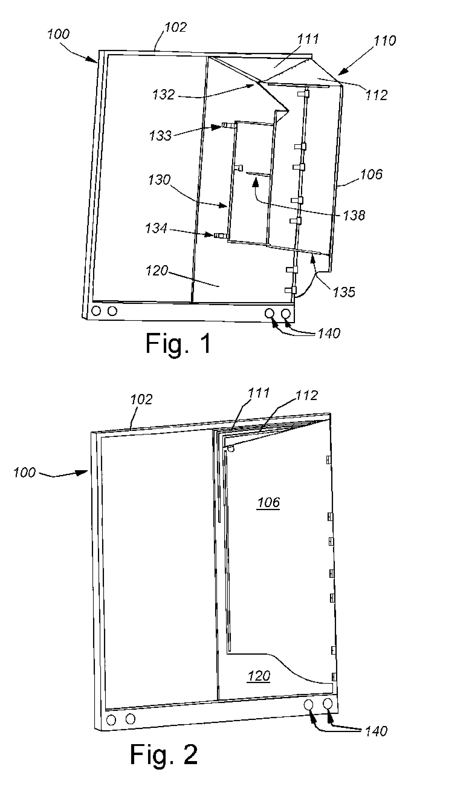
[0082]A rear-mounted aerodynamic structure for securing to a cargo body includes a three- or four-sided structure having a deployed position for assisting in improving aerodynamic efficiency of the cargo body. The cargo body can be the body of a trailer of a tractor-trailer vehicle or trailer towed behind a vehicle such as a truck. It can comprise a trailer body or other cargo body well-known in the art. In an illustrative embodiment, a spoiler “flow keeper” is mounted to a top surface of the rear of the cargo body, as an additional aerodynamic structure or as a standalone spoiler for cargo bodies. The three- or four-sided rear-mounted aerodynamic structure can comprise any of a variety of illustrative embodiments shown and described herein, as well as additional aerodynamic structures as shown and described herein.

I) Rear-Mounted Aerodynamic Structure Including Upper Panel and Side Panel

[0083]Reference is made to FIG. 1 showing a rear perspective view of a single door-mounted rear ...


PUM


Abstract

A rear-mounted aerodynamic structure for securing to a cargo body includes a three- or four-sided structure having a deployed position for assisting in improving aerodynamic efficiency of the cargo body. The cargo body can be the body of a trailer of a tractor-trailer vehicle or trailer towed behind a vehicle such as a truck. It can comprise a trailer body or other cargo body well-known in the art. A spoiler “flow keeper” mounted to a top surface of the rear of the cargo body, as additional aerodynamic structures or as a standalone spoiler for cargo bodies. The three- or four-sided rear-mounted aerodynamic structure can comprise any of a variety of illustrative embodiments shown and described herein.

Description

RELATED APPLICATIONS[0001]This application is a divisional of U.S. patent application Ser. No. 13 / 662,025, filed Oct. 26, 2012, entitled REAR-MOUNTED AERODYNAMIC STRUCTURES FOR CARGO BODIES, which application claims the benefit of U.S. Provisional Application Ser. No. 61 / 552,198, filed Oct. 27, 2011, entitled REAR-MOUNTED AERODYNAMIC STRUCTURES FOR CARGO BODIES, the entire disclosures of which is herein incorporated by reference.FIELD OF THE INVENTION[0002]The present invention relates to aerodynamic structures that are secured to the rear of cargo bodies, for example, on trucks or trailers, and other aerodynamic structures to improve airflow around the cargo body.BACKGROUND OF THE INVENTION[0003]Trucking is the primary mode of long-distance and short-haul transport for goods and materials in the United States, and many other countries. Trucks typically include a motorized cab in which the driver sits and operates the vehicle. The cab is attached to a box-like cargo section. Smaller...

Claims


Application Information

Patent Timeline
Patent Type & Authority Applications(United States)
IPC IPC(8): B62D35/00
CPCB62D35/001
Inventor SMITH, ANDREW F.GROSSMANN, JEFFREY J.HINRICHER, COURT S.CHOLNOKY, ROBERT R.DUNCANSON, AUSTIN A.
Owner STEMCO PROD INC
Why Eureka
Try Eureka