
Turbocharged engine

a turbocharged engine and engine technology, applied in the direction of machines/engines, mechanical equipment, electric control, etc., can solve the problems of increased pumping loss and degradation of fuel economy performance, and achieve the effect of improving the fuel economy performance of the engin

Active Publication Date: 2015-08-27
MAZDA MOTOR CORP
View PDF12 Cites 33 Cited by
  • Summary
  • Abstract
  • Description
  • Claims
  • Application Information

AI Technical Summary

Benefits of technology

The present invention aims to provide a turbocharged engine that can improve fuel economy performance while appropriately controlling the boost pressure to prevent excessive pressure. The engine uses a combination of an EGR valve and a waste gate valve to control the amount of exhaust gas flow and ultimately improve fuel efficiency. Overall, the invention allows for better engine performance while incorporating advanced boost pressure control techniques.

Problems solved by technology

Thereby, a pumping loss is increased, which leads to degradation in fuel economy performance.

Method used


Image

  • Turbocharged engine
  • Turbocharged engine
  • Turbocharged engine

Examples


Embodiment Construction

[0021](1) An Entire Configuration of the Engine

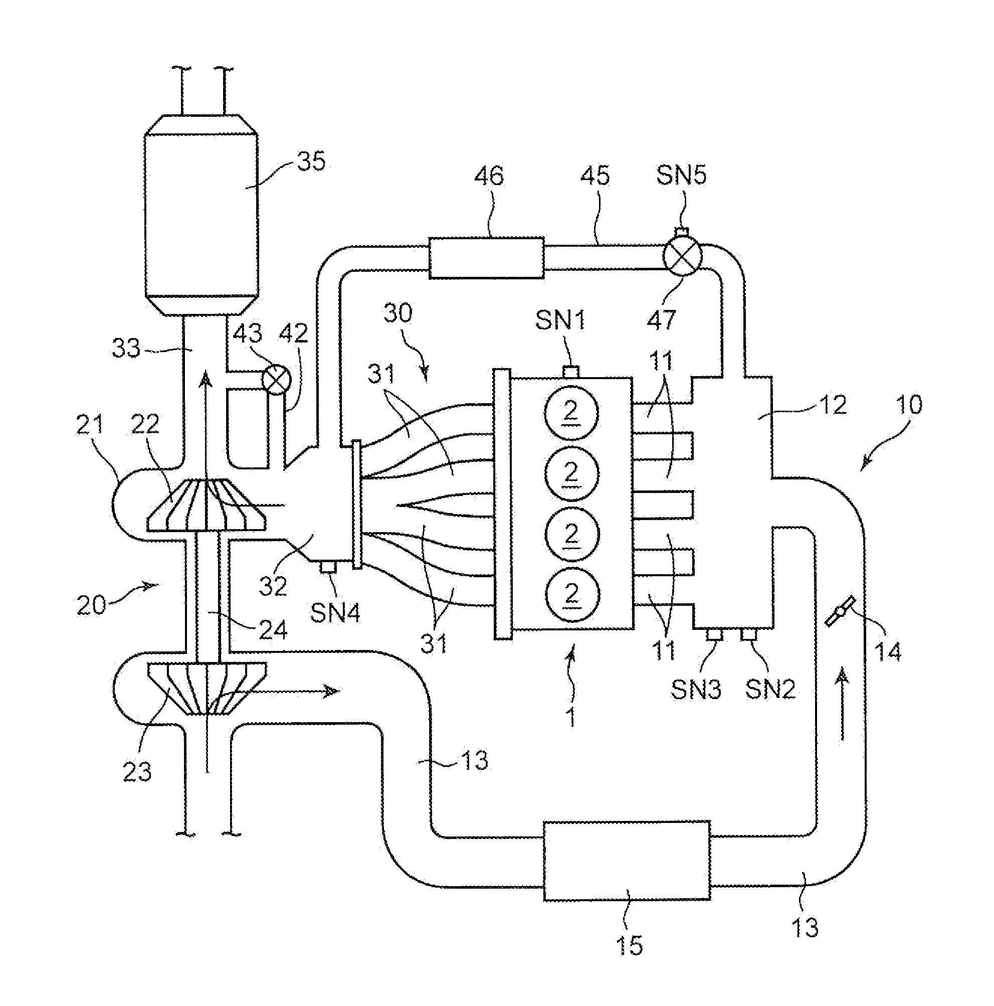
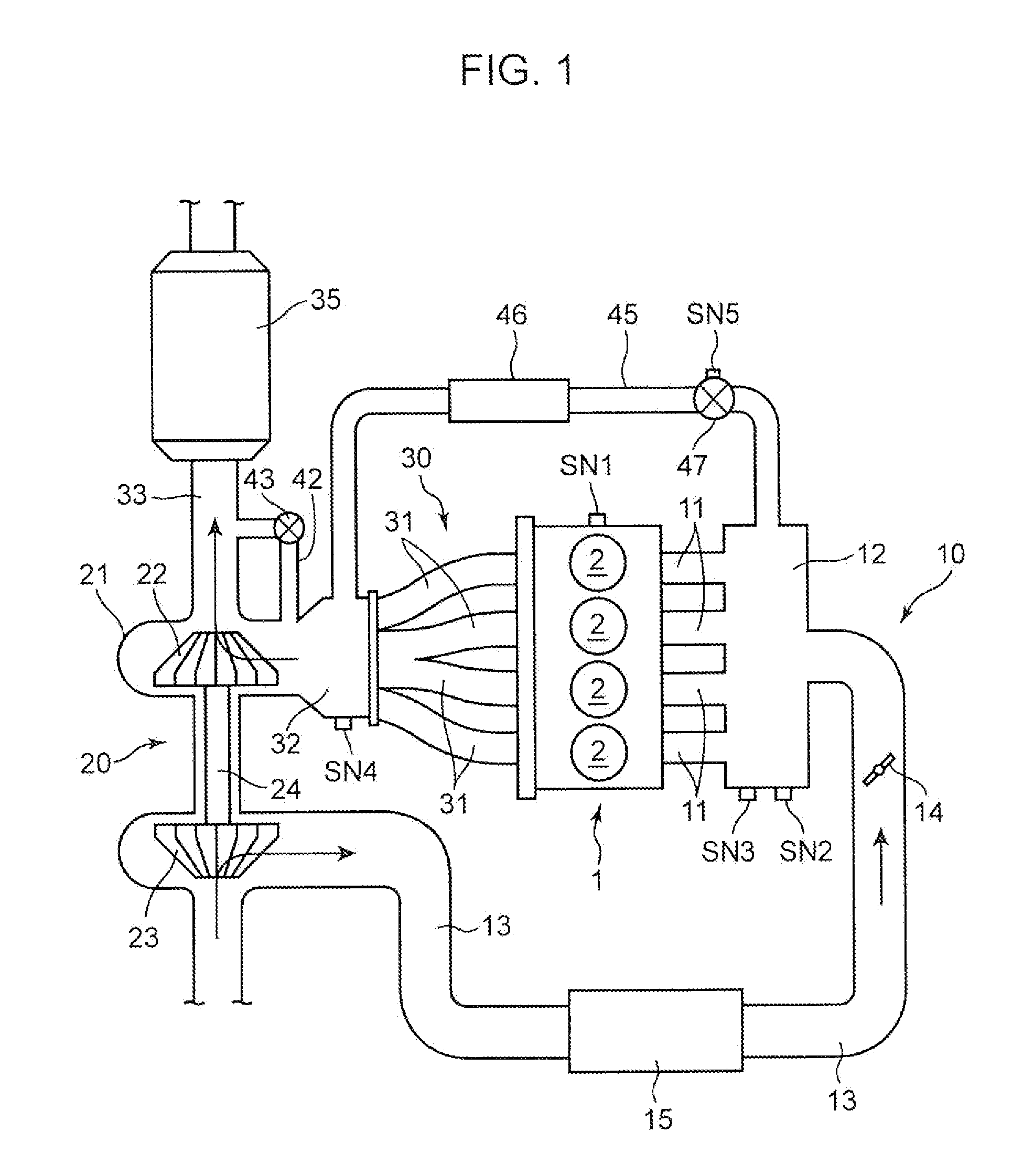
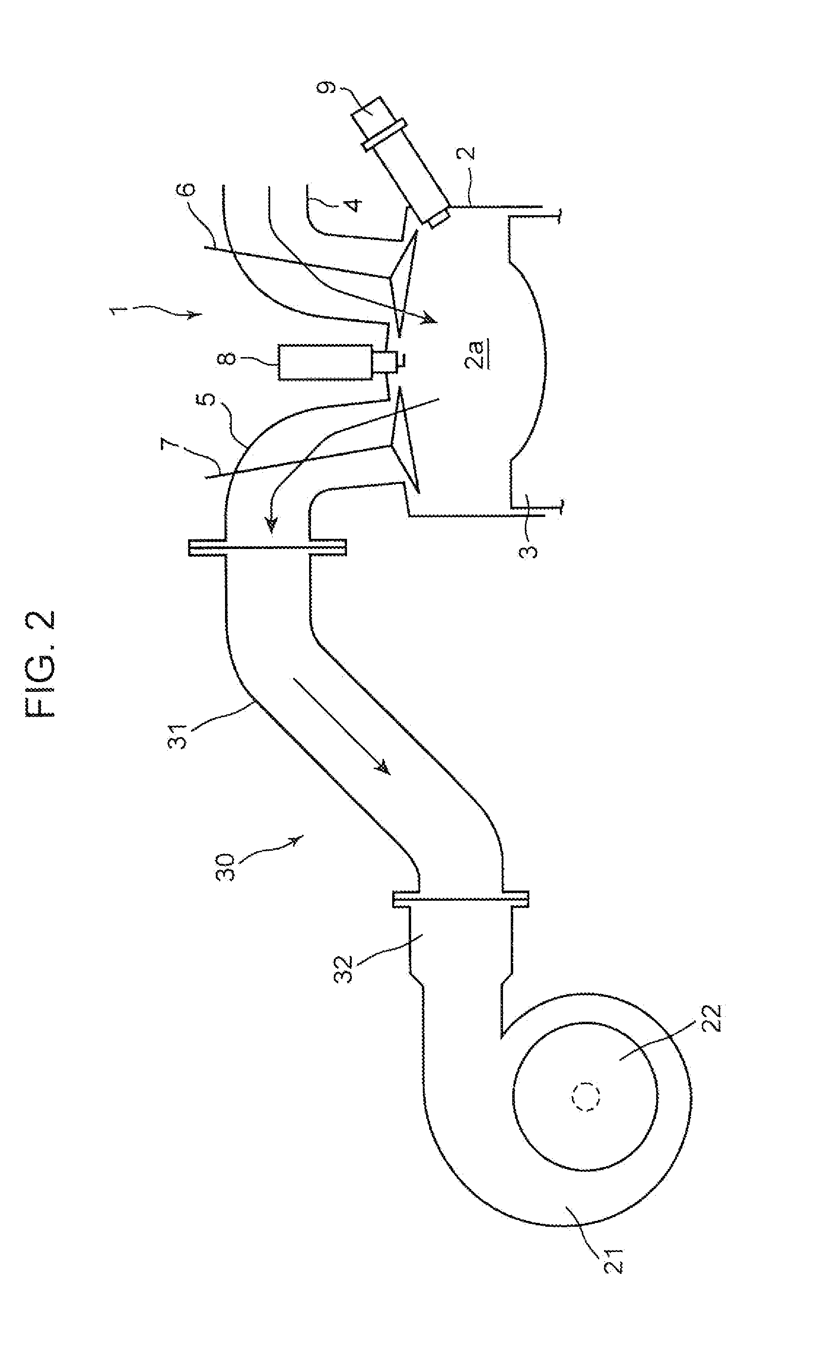
[0022]FIG. 1 and FIG. 2 illustrate a turbocharged engine of one embodiment of the present invention. The engine illustrated in the figures is a four-cycle spark-ignition multi-cylinder gasoline engine mounted on a vehicle as a power source for traveling. Specifically, the engine of the embodiment includes: an inline 4-cylinder engine body 1 having four cylinders 2 aligned in a row; an intake passage 10 for introducing air into each cylinder 2 of the engine body 1; an exhaust passage 30 for discharging exhaust gas generated in each cylinder 2 of the engine body 1; and a turbocharger 20 driven by energy of the exhaust gas.

[0023]In each cylinder 2 of the engine body 1, a piston 3 slidable back and forth is inserted, and a combustion chamber 2a is formed as a divided section above each piston 3. In the combustion chamber 2a, an air-fuel mixture of air and fuel injected from an injector 9 described later combusts, and expansion energy by the...


PUM


Abstract

An engine includes: a turbocharger including a turbine and a compressor; an EGR passage connecting an exhaust passage on an upstream side of the turbine and an air intake passage on a downstream side of the compressor; an EGR valve provided in the EGR passage; a bypass passage that bypasses the turbine; and a waste gate valve provided in the bypass passage. In the engine, when a boost pressure is increased to a limit pressure, a first boost pressure control is executed, in which the EGR valve is opened and the waste gate valve is closed. After the first boost pressure control starts, when an engine speed is increased to a prescribed value, a second boost pressure control is executed, in which the waste gate valve is opened in addition to the EGR valve.

Description

TECHNICAL FIELD[0001]The present invention relates to a turbocharged engine equipped with a turbocharger including: a turbine driven by energy of exhaust gas passing through an exhaust passage; and a compressor driven by the turbine to apply pressure to air in an intake passage.BACKGROUND ART[0002]The turbocharger aims at achieving high output of an engine using energy of exhaust gas discharged from the engine, and is widely adopted in various conventional engines.[0003]In the engine equipped with a turbocharger, since a boost pressure reaches a limit pressure when an engine speed is increased to a certain extent, it is necessary to perform a boost pressure control for preventing the boost pressure from exceeding the limit pressure.[0004]For instance, the turbocharged engine described in Patent Document 1 includes: a bypass passage that bypasses a turbine of the turbocharger; and a waste gate valve provided in the bypass passage. When the engine speed becomes equal to or higher than...

Claims


Application Information

Patent Timeline
Patent Type & Authority Applications(United States)
IPC IPC(8): F02B37/18F02D37/02F02M25/07
CPCF02B37/183F02D37/02F02M25/0706F02M25/0726F02D21/08F02D23/02F02D41/402F02P15/02F02D41/0007F02D41/005F02B17/005F02B23/104F02B29/0406F02B2023/085F02B2023/108F02M26/20F02M26/05F02M26/13F02M26/23Y02T10/12Y02T10/40F02B31/02
Inventor YAMAGATA, NAOYUKITSUJITA, SHUHEI
Owner MAZDA MOTOR CORP
Learn More