Power electronics cooling

a technology for power electronics and cooling systems, applied in domestic cooling devices, lighting and heating devices, semiconductor/solid-state device details, etc., can solve the problems of power electronic devices still remaining vulnerable, continuous challenges to the design and cooling performance of the employed cooling systems

Active Publication Date: 2015-08-27
HITACHI ENERGY SWITZERLAND AG
View PDF3 Cites 17 Cited by
  • Summary
  • Abstract
  • Description
  • Claims
  • Application Information

AI Technical Summary

Problems solved by technology

However, because power electronic devices still remain vulnerable to thermal problems more efficient cooling systems would be useful.
The further trend towards achieving higher power densities, which results in more compact power electronic

Method used


Image

  • Power electronics cooling
  • Power electronics cooling
  • Power electronics cooling

Examples


Embodiment Construction

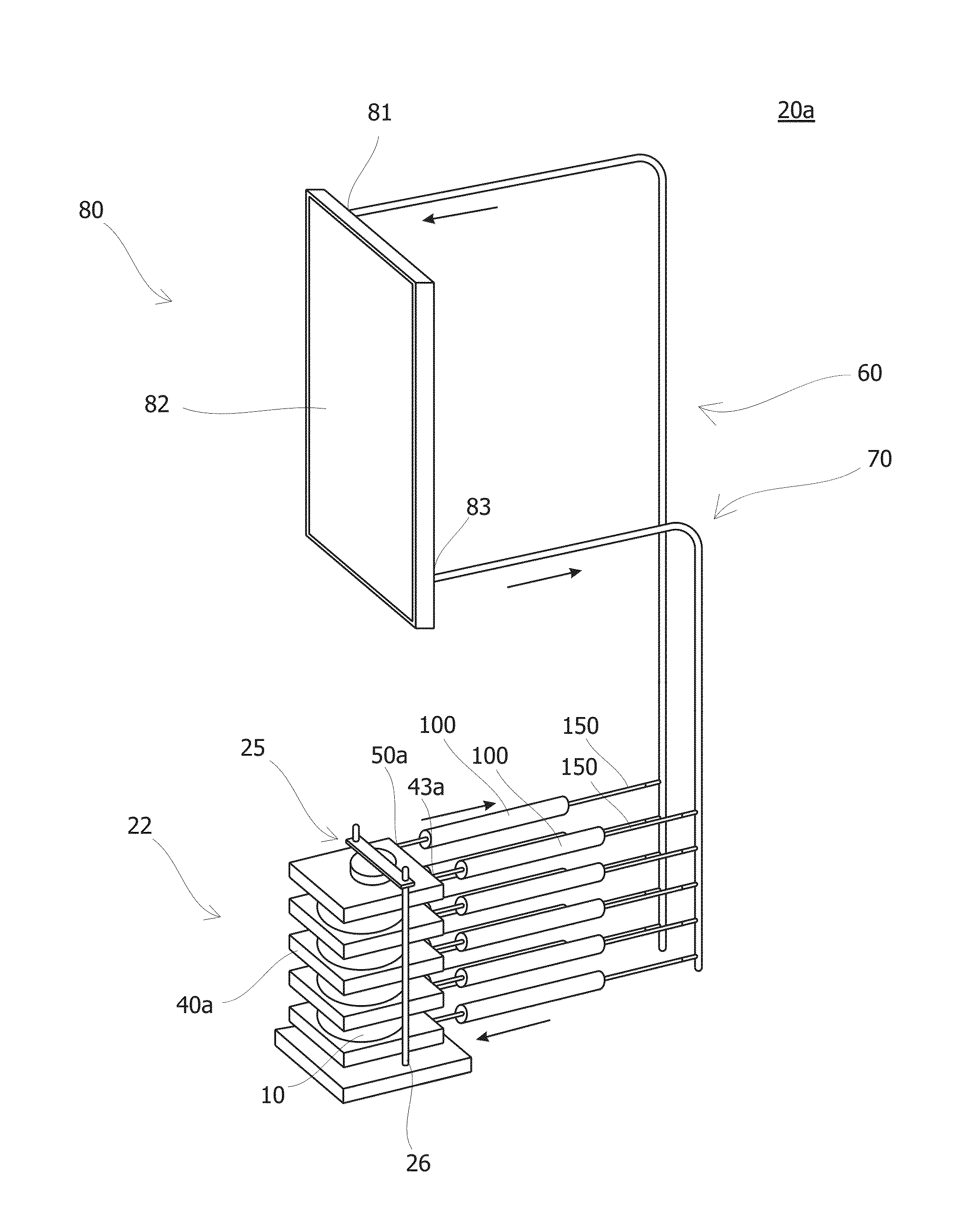
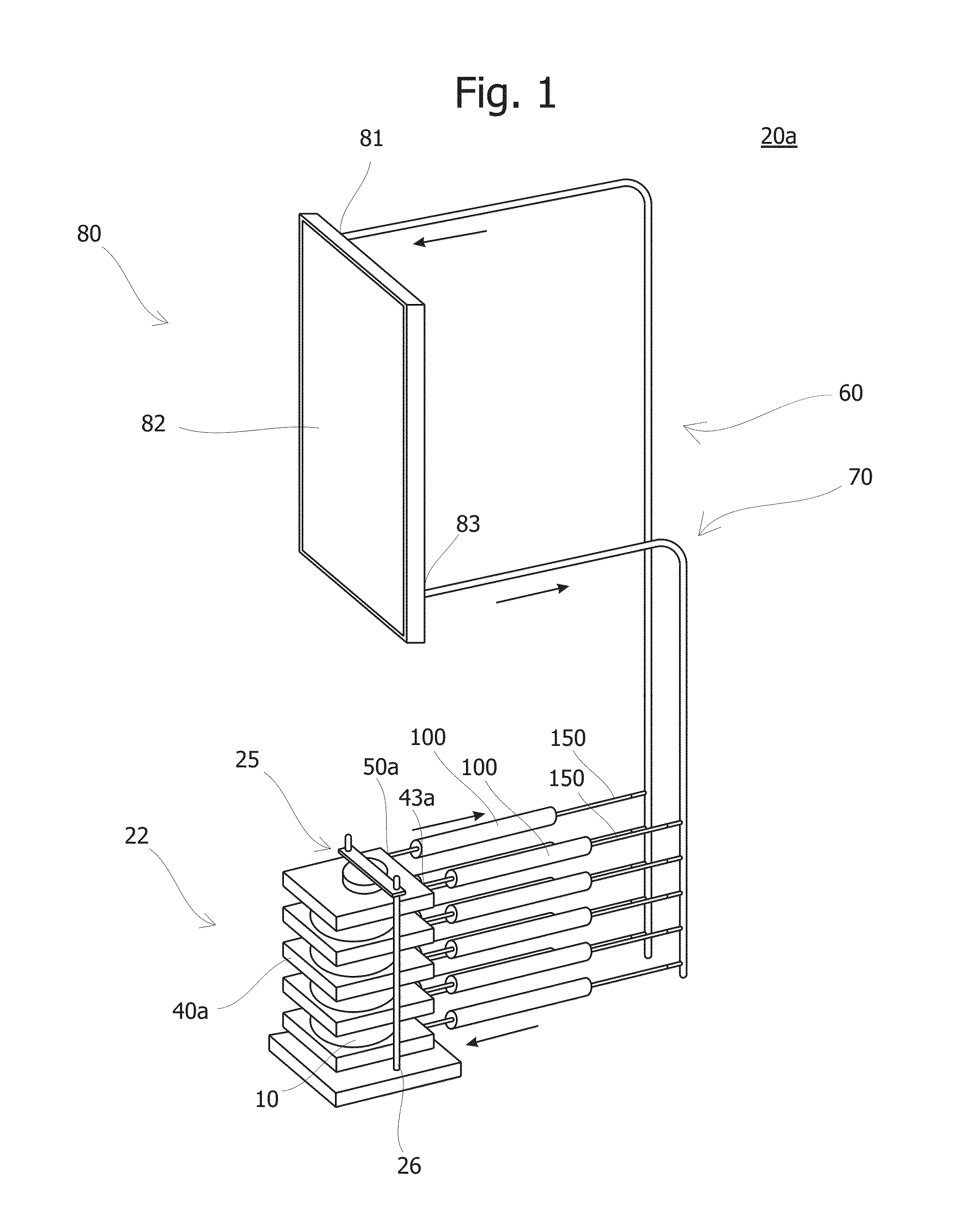
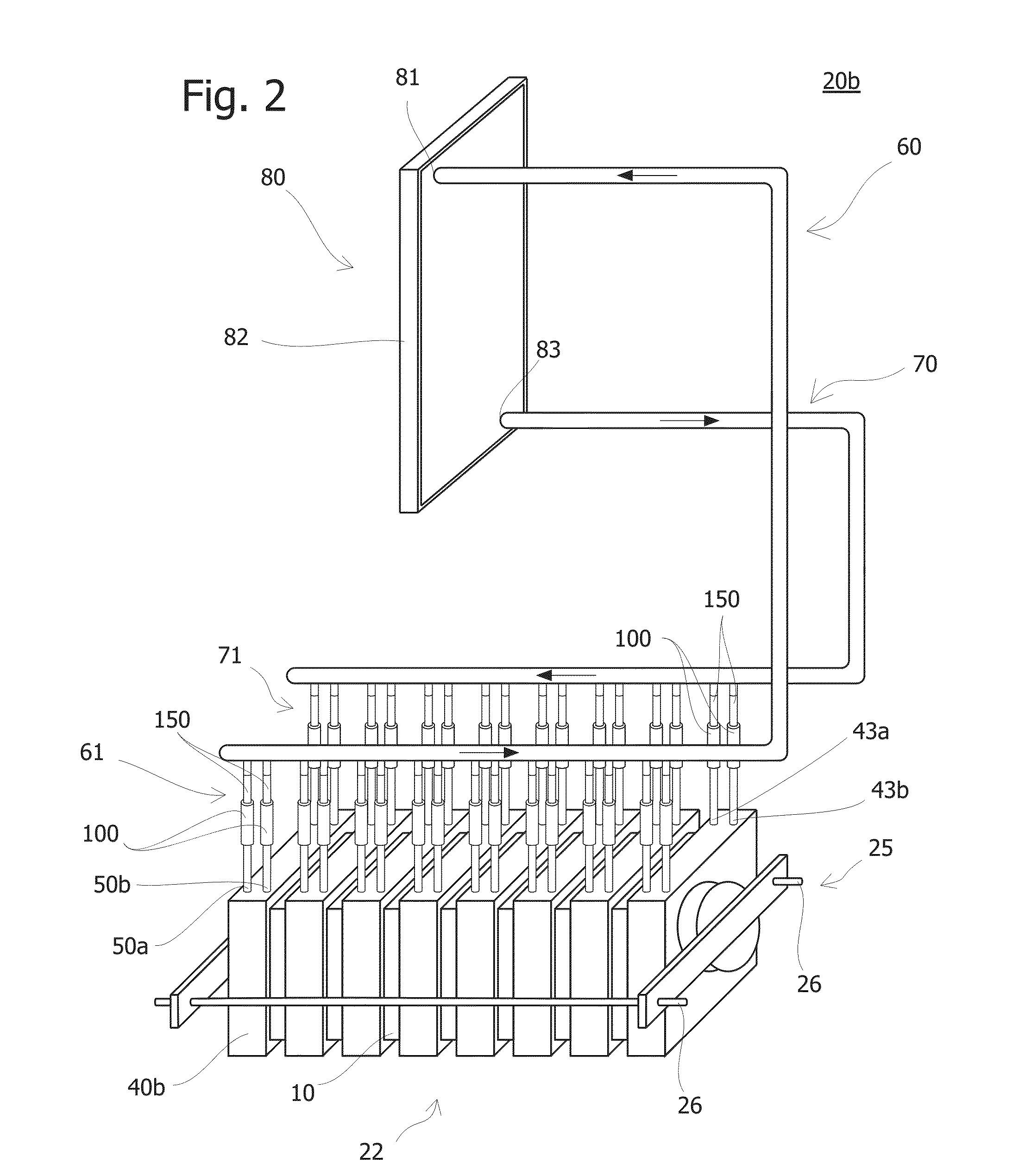
[0021]According to an exemplary embodiment of the present disclosure, an evaporating unit for cooling at least one heat emitting device by evaporation of a cooling fluid is provided. The evaporating unit includes a thermo-conducting wall that is thermally connectable to the at least one heat emitting device. A first inlet channel adapted for receiving the condensed cooling fluid from a condenser. A first fluid distributor fluidly connected to the first inlet channel for receiving the cooling fluid therefrom, and having a volume for collecting the cooling fluid therein. A first plurality of evaporation channels each having a first end and a second end, the first ends being fluidly connected to the first fluid distributor for receiving the cooling fluid therefrom, the first plurality of evaporation channels being in thermal contact with the at least one thermo-conducting wall such that in an operating state the cooling fluid therein is heated in the first plurality of evaporation chan...


PUM


Abstract

An exemplary evaporating unit for cooling a heat emitting device includes a cooling circuit having a stack of evaporating units arranged alternately with heat emitting devices. Each evaporating unit is connected to a condenser and includes a first inlet channel, a first plurality of evaporation channels, and a first outlet channel. The evaporating unit is designed for pre-heating the cooling fluid flowing therein.

Description

RELATED APPLICATION(S)[0001]This application claim priority under 35 U.S.C. §120 to International application PCT / EP2013 / 067826 filed on Aug. 28, 2013, designating the U.S., and claiming priority to European application 12182709.1 filed in Europe on Sep. 3, 2012. The content of each prior application is hereby incorporated by reference in its entirety.FIELD[0002]The subject matter described herein relates to cooling systems for power modules. For example, the subject matter relates to evaporators or two-phase coolers for electronic components, to cooling systems using such evaporators and to methods for cooling of electronic components such as, power semiconductors.BACKGROUND INFORMATION[0003]Cooling is can be an important aspect in the design of any electrical product, such as IGBT (insulated gate bipolar transistor) based products, e.g., DC-breakers, as heat is inevitably generated by the current flowing through the electrical circuits. In recent years there has been a tendency of...

Claims


Application Information

Patent Timeline
IPC IPC(8): F25B39/02
CPCF25B39/02F28D15/0266F28F7/02F28F9/001F28F9/22H01L23/4012H01L23/427H01L2924/0002
Inventor BLOMBERG, ANDERSAGOSTINI, BRUNONI, JINGHAFNER, JURGENHABERT, MATHIEU
Owner HITACHI ENERGY SWITZERLAND AG
Why Eureka
Try Eureka